Microscopic three-dimensional reconstruction method

A technology of three-dimensional reconstruction and optical microscope, applied in the field of micro vision, can solve the problems of precision and speed limitation of precision lifting platform, system complexity and so on

Inactive Publication Date: 2014-02-26
BEIHANG UNIV
View PDF5 Cites 14 Cited by
  • Summary
  • Abstract
  • Description
  • Claims
  • Application Information

AI Technical Summary

Problems solved by technology

[0003] Use a precision lifting platform to control the object under observation or the microscope lens to move up and down, and simultaneously take images of the object and record the height corresponding to each image. In the later stage, the 3D reconstruction algorithm can be used to recover the 3D appearance information to achieve 3D reconstruction. The method is limited by the accuracy and speed of the precision lifting platform, and the system is relatively complicated

Method used


Image

  • Microscopic three-dimensional reconstruction method
  • Microscopic three-dimensional reconstruction method
  • Microscopic three-dimensional reconstruction method

Examples


Embodiment Construction

[0014] Embodiments according to the present invention will be described below with reference to the drawings. In the drawings, like reference numerals denote like elements throughout.

[0015] The optical path of the microscope imaging system according to the embodiment of the present invention is described with reference to the accompanying drawings.

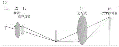
[0016] figure 1 The optical path diagram of the microscope system according to the embodiment of the present invention is shown. Such as figure 1 As shown, the optical path 10 of the microscope system includes a measured object 11 , an objective lens 12 , a liquid lens 13 , an adapter mirror 14 and a detector CCD15 . The liquid lens 13 is placed between the objective lens 12 and the adapter lens 14 .

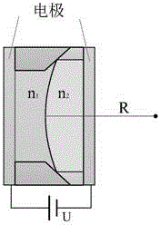
[0017] figure 2 The flow chart of the method of the embodiment of the present invention is shown. By using the liquid lens as the zoom element, a series of focusing is performed on the continuous depth range of the observed...


PUM


Abstract

A microscopic three-dimensional reconstruction method is provided. The microscopic three-dimensional reconstruction method comprises the following steps that: a liquid lens of which the focal length can be controlled through voltage is additionally mounted in an optical path of a digital microscope; with the liquid lens adopted as a focal length-varying element, a series of focusing is performed in a continuous depth range of an observed object so as to shoot a series of continuous local focus images; height differences between the local focus images can be obtained through the calibration of the liquid lens in advance; three-dimensional information of a measured object is extracted from the series of images through a three-dimensional reconstruction algorithm, such that a three-dimensional model of the object is obtained; and a two-dimensional clear image is obtained through image fusion, and the two-dimensional clear image, adopted as texture, is bonded on the three-dimensional model, and three-dimensional reconstruction of the object is accomplished. With the microscopic three-dimensional reconstruction method adopted, limitation on object observation in a two-dimensional direction because of too small depth of field of a microscopic optical system can be effectively eliminated.

Description

technical field [0001] The invention relates to the field of micro vision in photoelectric detection technology, and more specifically relates to a device and method for obtaining a micro three-dimensional reconstruction model. Background technique [0002] Because the depth of field of the optical microscope is too short, there are limitations in observing the depth information of the object. When the surface of the object is uneven, if the depth of field of the microscope is short, the image of the captured object will be partially blurred. Therefore, the traditional 3D reconstruction Methods such as binocular vision 3D reconstruction and structured light 3D reconstruction cannot be applied to microscopic 3D reconstruction. [0003] Use a precision lifting platform to control the object under observation or the microscope lens to move up and down, and simultaneously take images of the object and record the height corresponding to each image. In the later stage, the 3D reco...

Claims


Application Information

Patent Timeline
Patent Type & Authority Applications(China)
IPC IPC(8): G06T15/00G06T17/00G01B9/04
Inventor 屈玉福杨海娟毛建森马诗洁
Owner BEIHANG UNIV
Why Eureka
Try Eureka