Optical unit and endoscope
A technology of optical units and optical components, applied in the field of endoscopy, can solve problems such as difficulty in solving
- Summary
- Abstract
- Description
- Claims
- Application Information
AI Technical Summary
Problems solved by technology
Method used
Image

Examples
no. 1 Embodiment approach >
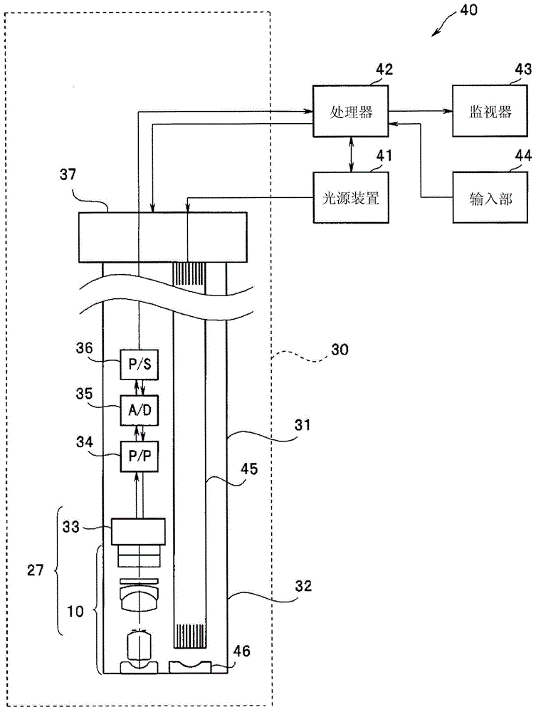
[0021] First, the optical unit 10 and the endoscope 30 including the optical unit 10 according to the first embodiment will be described. Such as figure 1 As shown, the endoscope 30 together with the light source device 41 and the processor 42 constitute an endoscope system 40 . The endoscope 30 has an insertion portion 31 inserted into the body of a subject. The light source device 41 generates illumination light for illuminating the inside of the body. The processor 42 performs various signal processing, and controls the endoscope system 40 .
[0022] An optical fiber 45 for guiding illumination light from a light source device 41 to a distal end portion 32 penetrates the insertion portion 31 of the endoscope 30 , and illuminates the inside of the body via an illumination optical system 46 . Also in figure 1 In the illumination optical system 46, only the object side lens is shown.
[0023] The processor 42 can be used as an endoscope system suitable for the purpose by ...
no. 2 Embodiment approach >
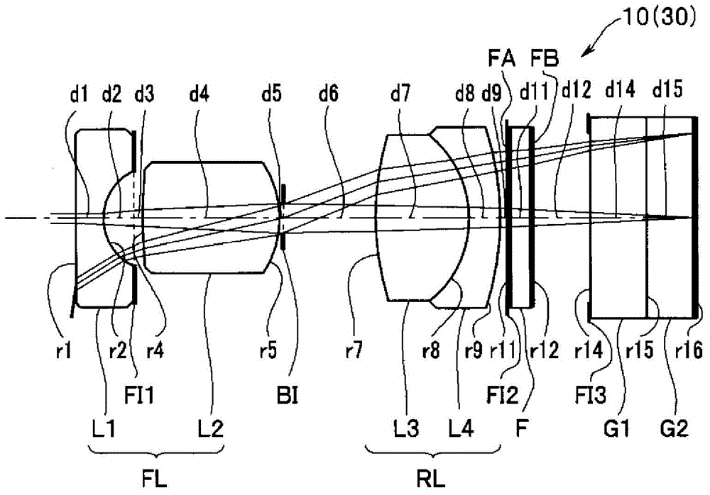
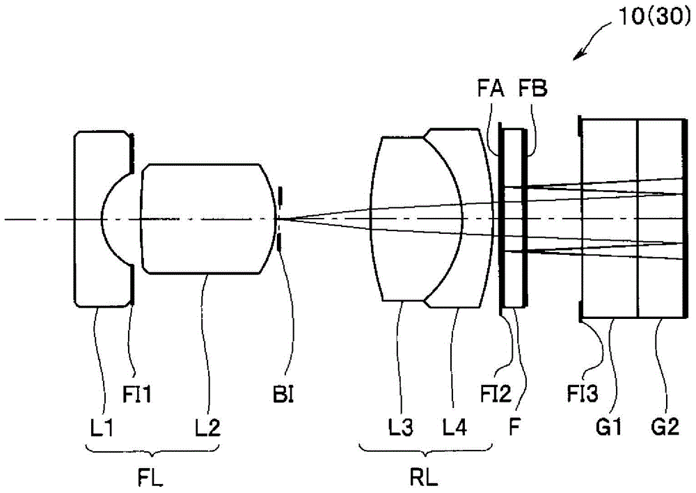
[0047] Such as Figure 6 and Figure 7 As shown, the optical unit 10A of the endoscope 30A of the second embodiment includes a front lens group FL (a plano-concave first negative lens L1, a convex second positive lens L2 toward the image plane, and a front lens group FL) from the object side. side convex third positive lens L3), brightness aperture BI, rear lens group RL (biconvex fourth positive lens L4, biconvex fifth positive lens L5, and convex sixth negative lens L6 ), infrared absorption filter F1, filter F2, cover glass G1 and CCD cover glass G2. The fifth positive lens L5 is bonded to the sixth negative lens L6, and the cover glass G1 is bonded to the CCD cover glass G2. In addition, FI1 to FI4 are stray light blocking apertures.
[0048] An LD laser cut film FA is formed on the object side of the filter F2, and a YAG laser cut film FB is formed on the image side. The third positive lens L3 can move in the direction of the optical axis to perform focus adjustment. ...
no. 3 Embodiment approach >
[0054] Such as Figure 8 and Figure 9 As shown, the optical unit 10B of the endoscope 30B of the third embodiment includes a front lens group FL (plano-concave first negative lens L1 ), an infrared absorption filter F1 , and a first negative lens L1 convex toward the object side in order from the object side. 2 Positive lens L2, brightness diaphragm BI, rear lens group RL (biconvex third positive lens L3, biconvex fourth positive lens L4, and fifth negative lens L5 convex toward the image plane side), filter F2 , Cover glass G1 and CCD cover glass G2. The fourth positive lens L4 is bonded to the fifth negative lens L5, and the cover glass G1 is bonded to the CCD cover glass G2. In addition, FI1 to FI5 are stray light blocking apertures.
[0055] An LD laser cut film FA is formed on the object side of the filter F2 which is a transparent parallel flat plate, and a YAG laser cut film FB is formed on the image side. The focus of the second positive lens L2 can be adjusted by...
PUM
 Abstract
Description
Claims
Application Information
 - R&D
- Intellectual Property
- Life Sciences
- Materials
- Tech Scout
- Unparalleled Data Quality
- Higher Quality Content
- 60% Fewer Hallucinations
Browse by: Latest US Patents, China's latest patents, Technical Efficacy Thesaurus, Application Domain, Technology Topic, Popular Technical Reports.
© 2025 PatSnap. All rights reserved.Legal|Privacy policy|Modern Slavery Act Transparency Statement|Sitemap|About US| Contact US: help@patsnap.com