
Implement method of rake convergence drill bit and rake convergence drill bit

An implementation method and drill technology, applied in the field of hole machining tools, can solve the problems of increasing cutting torque, different chip deformation, hindering chip curling and discharge, etc., to reduce cutting force, smooth chip removal, and improve service life. Effect

Inactive Publication Date: 2014-03-05
天津市量具刃具有限公司
View PDF6 Cites 4 Cited by
  • Summary
  • Abstract
  • Description
  • Claims
  • Application Information

AI Technical Summary

Problems solved by technology

In addition, the large rake angle change of the main cutting edge causes the cutting force and chip deformation at each point to be significantly different, resulting in additional chip deformation stress, increasing the cutting torque and hindering the curling and discharge of chips

Method used


Image

  • Implement method of rake convergence drill bit and rake convergence drill bit
  • Implement method of rake convergence drill bit and rake convergence drill bit
  • Implement method of rake convergence drill bit and rake convergence drill bit

Examples


Embodiment Construction

[0012] In order to make the purpose, technical solutions and beneficial effects of the present invention more clear, the present invention will be further described in detail below in conjunction with the examples. It should be understood that the specific examples described here are only used to explain the present invention, and are not intended to limit the protection scope of the present invention.

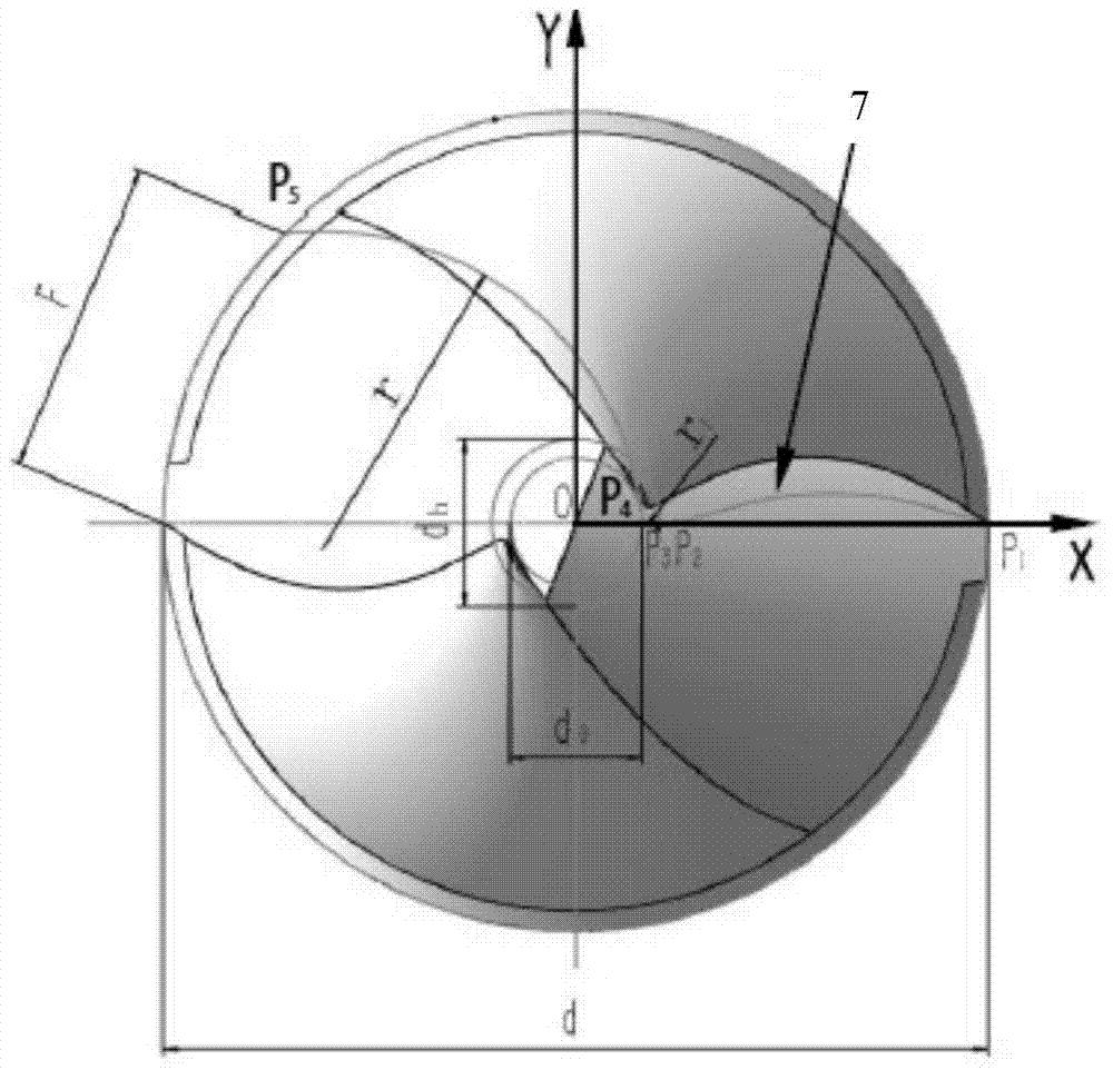
[0013] like image 3 , Figure 4 As shown, in order to achieve the purpose of the present invention, the present invention provides a method for realizing a rake angle converging drill bit, and the method includes the step of designing the end surface sectional curve of the main cutting edge as a sinusoidal curve.

[0014] The invention also provides a rake angle converging drill bit, the end section of the drill bit has a sinusoidal cutting edge section.

[0015] The present invention changes the large rake angle of the main cutting edge of the ordinary drill bit, which is ...


PUM


Abstract

The invention discloses an implement method of a rake convergence drill bit. The implement method comprises the step of designing the section curve of the end face of a main cutting edge to be a sine curve. The invention further discloses the rake convergence drill bit. The end section of the drill bit is the section of the cutting edge with the sine curve. By means of the implement method of the rake convergence drill bit and the rake convergence drill bit, the shortcomings that the rakes of a main cutting edge of a traditional drill bit change largely, and cutting distribution is not facilitated are overcome, the too large rakes at the outer edge are reduced, the strength and the cooling capacity of the cutting edge are enhanced, and the service life of the drill bit is obviously prolonged; the cutting state of the negative rakes, with the large absolute value, at a drill core is changed, and abrasion and cutting force are reduced; cutting deformation tends to be consistent due to the approximately equal rakes of the main cutting edge, and resistance caused by additional deformation is avoided. In addition, the space for containing cuttings is increased due to the groove back convex curve of the section of a groove, the cuttings are discharged more smoothly, and deep holes can be machined easily.

Description

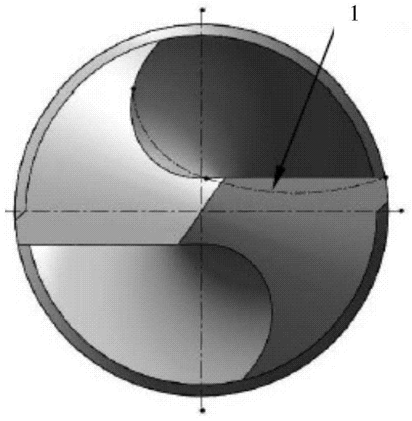
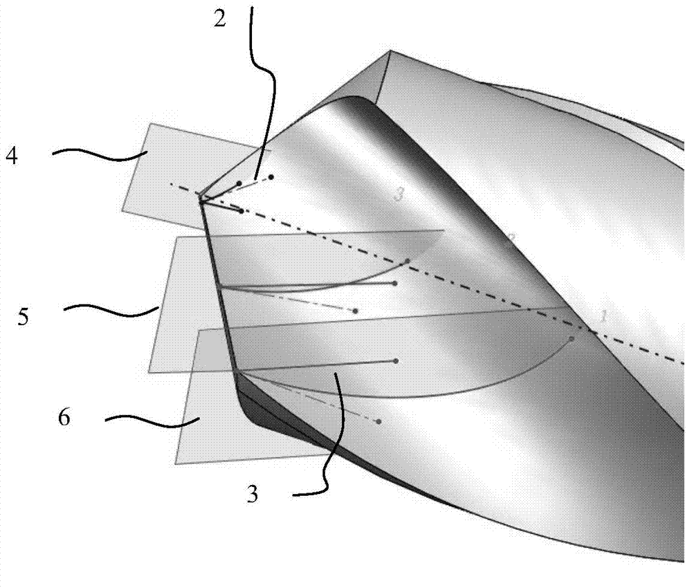
technical field [0001] The invention relates to a hole processing tool, in particular to a method for realizing a rake angle converging drill bit and the rake angle converging drill bit. Background technique [0002] It is known that the main cutting edge of a common twist drill is a straight line, and the cross section of the groove end face is a concave curve, as shown in the attached figure 1 shown. From the outer edge of the drill to the drill core, the rake angle of the main cutting edge becomes smaller as the radius of each point decreases, and decreases sharply near the drill core. Usually, it changes from 30° at the outer edge to -30° near the drill core, as shown in the attached figure 2 shown. If the rake angle is too large at the outer edge, the strength of the cutting edge will be reduced and the heat dissipation capacity will be weakened; if the rake angle near the drill core is too small, the extrusion effect will be significant during cutting, and the chip...

Claims


Application Information

Patent Timeline
Patent Type & Authority Applications(China)
IPC IPC(8): B23B51/02
CPCB23B51/02
Inventor 王焯林
Owner 天津市量具刃具有限公司
Learn More