
Energy dissipation flood discharging device

A flood discharge and energy dissipation technology, applied in water conservancy projects, marine engineering, coastline protection, etc., can solve the problems of loss of spinning effect, increased construction cost, surface damage of spinning tunnels, etc., to achieve smooth energy conversion and improved use. The effect of life and construction cost saving

Inactive Publication Date: 2014-03-05
HOHAI UNIV
View PDF4 Cites 26 Cited by
  • Summary
  • Abstract
  • Description
  • Claims
  • Application Information

AI Technical Summary

Problems solved by technology

Although the above-mentioned flood discharge tunnel can realize energy dissipation, in actual use, because the water does not receive any energy dissipation when it falls in the flow shaft, it will impact into the swirl tunnel at a relatively high speed, and long-term use will cause the The surface of the spin hole is damaged and loses the function of spinning
Moreover, the above-mentioned flood discharge tunnel needs a long swirl tunnel section, a water cushion pond section and a water retreat tunnel to completely realize energy dissipation, which must be realized over a long distance.
This increases construction costs

Method used


Image

  • Energy dissipation flood discharging device
  • Energy dissipation flood discharging device

Examples


Embodiment Construction

[0016] The present invention will be further described below in conjunction with accompanying drawing.

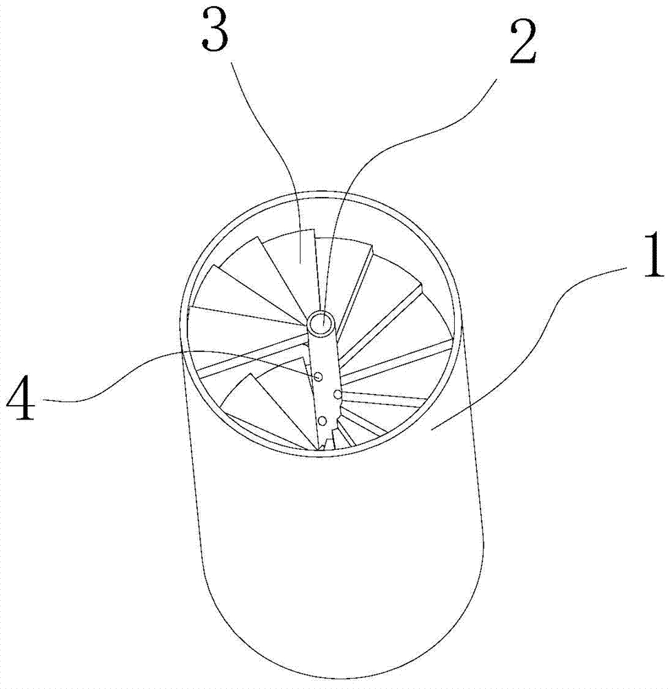
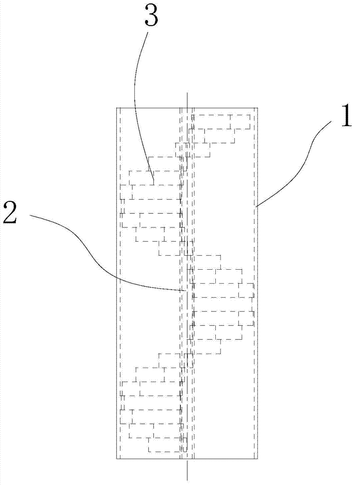
[0017] Such as figure 1 with figure 2 As shown, the present invention includes a flood discharge tunnel 1, and also includes a central axis 2 and a spiral flow channel 3, the central axis 2 is arranged at the axis of the flood discharge tunnel 1, and the spiral flow channel 3 is arranged with the central axis 2 as the axis, so The inlet of the spiral channel 3 communicates with the inlet of the flood discharge tunnel 1, and the outlet of the spiral channel 3 communicates with the outlet of the flood discharge tunnel 1. The spiral flow channel 3 has a spiral shape as a whole, and the surface of the flow channel of the spiral flow channel 3 can be set in different shapes, such as wavy, flat and stepped, and blocks can also be uniformly arranged on the surface of the flow channel along the flow direction. The above-mentioned structure can be set according to different situa...


PUM


Abstract

The invention relates to the field of water conservancy and hydropower, in particular an energy dissipation flood discharging device. The energy dissipation flood discharging device is gentler in the energy dissipation process. The energy dissipation flood discharging device comprises a flood discharging hole and further comprises a central shaft and a spiral flow channel. The central shaft is arranged at the axis position of the flood discharging hole, the spiral flow channel is arranged with the central shaft as the axis, an inlet of the spiral flow channel is communicated with an inlet of the flood discharging hole, and an outlet of the spiral flow channel is communicated with an outlet of the flood discharging hole. When water flow enters the structure, the water flow moves spirally along the spiral flow channel and finally arrives at the bottom of the structure. The spiral flow channel is long and many curves exist, so that the water flow is acted by friction force for a long time, and since the water flow collides with the spiral flow channel, a large amount of gravitational potential energy is transferred into heat energy. Thus, the purpose of energy dissipation is achieved.

Description

technical field [0001] The invention relates to the field of water conservancy and hydropower, in particular to an energy dissipation and flood discharge device. Background technique [0002] In water conservancy construction, flood discharge structures are usually used. During the flood discharge process, due to the height difference, water will hit the lower ground, which will cause serious damage to the lower ground during long-term use. In view of this problem, an energy dissipation flood discharge device is currently designed so that the water is rubbed and collides with each other during the falling process to consume the gravitational potential energy and kinetic energy of the water and reduce the impact of the water on the ground. [0003] For example, in the patent No. 200820029327.1 and the publication date of April 1, 2009, the Chinese patent "Horizontal Swirling Energy Dissipating Floodway", a swirl hole is provided at the bottom of the flow shaft, and the water ...

Claims


Application Information

Patent Timeline
IPC IPC(8): E02B8/06
Inventor 张胤
Owner HOHAI UNIV
Learn More