Expansion joint used for cyclone separator

A technology of cyclone separator and expansion joint, which is applied to expansion compensation devices for pipelines, pipes/pipe joints/fittings, mechanical equipment, etc. Problems such as the decline of separation efficiency can ensure long-term safe operation, solve the problem of cracking or even falling off of connecting welds, and improve the ability to compensate for multi-directional thermal expansion displacement.

Active Publication Date: 2014-03-05
LUOYANG SUNRUI SPECIAL EQUIP
View PDF9 Cites 3 Cited by
  • Summary
  • Abstract
  • Description
  • Claims
  • Application Information

AI Technical Summary

Problems solved by technology

In recent years, due to the development of catalytic cracking of heavy oil, the regeneration reaction temperature has increased from 640-660 °C in the past to 700-720 °C or even higher in the catalytic cracking of distillate oil. In addition, the high-speed impact of the flue gas at an intake velocity of about 25m / s will cause serious deformation of the internal parts such as the baffle, and the expansion joint of the central flue gas inlet pipe will be cracked, resulting in a serious drop in the separation efficiency of the three-rotation, affecting the smoke machine safe operation of
[0004] Conventional expansion joint structure types used inside cyclone separators are shown in figure 2 , the expansion joint is a single axial type, which is composed of outlet pipe 9, inlet pipe 1, bellows 4 and guide tube 12, and is mainly used to absorb axial displacement; the bellows are a group, and the bellows The two ends of the two ends are respectively connected with the outlet pipe 9 and the inlet pipe 1; the guide tube 12 is located in the bellows, and there is a gap between the guide tube and the bellows; one end of the guide tube passes through the lining retaining ring 13 and The inlet end pipe 1 is connected, and the other end is a cantilever structure, which is located in the outlet end pipe 9; a detachable protective cover 6 is set outside the expansion joint to prevent the external medium from directly eroding the bellows and protect the bellows; the above structure expands The types of joint failure are as follows: First, under the action of high temperature and high stress, the bellows will crack due to excessive deformation; although the pressure difference between the inside and outside of the bellows is very small, because the inside and outside of the bellows are not connected, the design needs to be unilateral Pressure design, so in order to ensure high temperature and high design pressure on one side, the wall thickness of the bellows is thicker to meet the strength requirements, so its working stiffness is relatively large. Under the action of pressure, the expansion joint acts on the connecting equipment at both ends ( The acting force is the sum of the pressure thrust generated by the pressure acting on the bellows of the expansion joint and the elastic reaction force caused by the compensation displacement of the expansion joint, and the elastic reaction force mainly caused by the compensation displacement of the expansion joint) is also large; at the same time, because the bellows has only one Group, which mainly compensates axial displacement, and has limited ability to compensate lateral displacement (large lateral stiffness). If large lateral displacement is to be compensated, it will generate a large force on the equipment; the second is that high-speed flowing flue gas encounters expansion In addition, the cantilever end of the guide tube is washed by the air flow, which will cause high-frequency vibration, and the corrosion of the flue gas medium will easily cause cracks in the connection weld between the guide tube and the outlet pipe. In severe cases, it may even cause the guide tube to fall off and lose the protective effect on the bellows
Therefore, the structure of the above expansion joint will affect the long-term safe operation of the equipment and itself

Method used


Image

  • Expansion joint used for cyclone separator
  • Expansion joint used for cyclone separator
  • Expansion joint used for cyclone separator

Examples


Embodiment Construction

[0019] The present invention is described in conjunction with accompanying drawing and specific embodiment:

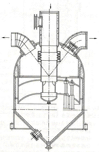
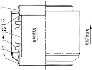
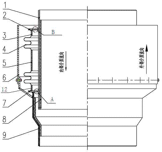
[0020] Such as image 3 As shown, an expansion joint for a cyclone separator device, the expansion joint includes an outlet end pipe 9, an inlet end pipe 1 and a corrugated pipe 4 that act as a flow guide; the inlet end pipe 1 that acts as a flow guide One end of the pipe is connected to the equipment through a connecting pipe, and the other end is located in the outlet pipe 9; the inner diameter of the inlet pipe 1 and the connecting pipe that act as a guide is the same as the inner diameter of the connected equipment, so that the flue gas can pass through smoothly The expansion joint avoids the impact of high-speed flue gas on the guide tube, which is beneficial to the protection of the bellows; the inner walls of the inlet end pipe 1 and the outlet end pipe 9 that play a role in diversion have wear-resistant linings 8; the bellows 4 is two groups, and the bellows 4...


PUM


Abstract

The invention belongs to the technical field of petrifaction expansion joint compensation, and provides an expansion joint used for a cyclone separator. The expansion joint used for the cyclone separator comprises an outlet end pipe (9), an inlet end pipe (1) and a corrugated tube (4). One end of the inlet end pipe (1) is connected with a device, the inner diameter of the inlet end pipe (1) is the same as the inner diameter of the device connected with the inlet end pipe (1), the other end of the inlet end pipe (1) is located in the outlet end pipe (9), and therefore smoke can stably pass through the expansion joint, and impact of high-speed smoke on the inlet end pipe (1) can be avoided. The two ends of the corrugated tube (4) are provided with a supporting annular plate I (7) and a supporting annular plate II (2) respectively. A gap exists between the supporting annular plate I (7) and the inlet end pipe (1), and therefore gas pressure can enter the gap, and the displacement compensation function can be achieved. A plurality of air holes (10) are formed in the supporting annular plate II (2), and therefore the internal pressure of the corrugated tube and the external pressure of the corrugated tube can be communicated, and the design pressure and the work pressure of the corrugated tube can be lowered.

Description

technical field [0001] The invention belongs to the technical field of petrochemical expansion joint compensation, and in particular relates to an expansion joint for a cyclone separator device. Background technique [0002] The flue gas from the regenerator of the FCC refining catalytic cracking unit contains many fine catalyst particles with an average diameter of about 15 microns. When using the smoke machine to recover energy, in order to reduce the erosion of the solid particles in the flue gas on the smoke machine blades , wear and tear, to ensure the long-term safe operation of the hood. At present, three-stage cyclone separators are often used to separate the catalyst particles in the flue gas, so that the content of catalyst particles with a particle size greater than 10 microns in the flue gas is less than 3%, and the catalyst dust in the flue gas The content is less than 100 mg / NL; the flue gas separated by the three-stage cyclone separator enters the flue gas tur...

Claims


Application Information

Patent Timeline
Patent Type & Authority Applications(China)
IPC IPC(8): F16L51/03
CPCF16L51/03
Inventor 张爱琴刘海威王宁付强
Owner LUOYANG SUNRUI SPECIAL EQUIP
Why Eureka
Try Eureka