Optical interferometer used for detecting outer surface of cylinder

A technology of optical interference and outer surface, which is applied in the field of optical interferometer, can solve the problems of not being able to obtain the three-dimensional surface shape at one time, the influence of the interferometer detection accuracy and reliability, and the deviation of the detection shape, so as to improve the test efficiency and keep the outside world The effect of low environmental requirements and improved accuracy and reliability

Active Publication Date: 2014-03-05
苏州慧利仪器有限责任公司 +2
View PDF4 Cites 9 Cited by
  • Summary
  • Abstract
  • Description
  • Claims
  • Application Information

AI Technical Summary

Problems solved by technology

[0003] However, existing interferometers often detect deviations in surface shape, such as curved or partially curved or concave-convex areas. For the detection of three-dimensional surface shape, repeated inspections are required, and a...

Method used


Image

  • Optical interferometer used for detecting outer surface of cylinder
  • Optical interferometer used for detecting outer surface of cylinder
  • Optical interferometer used for detecting outer surface of cylinder

Examples


Embodiment 1

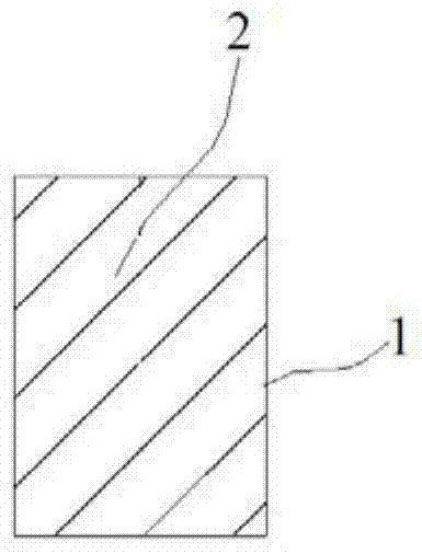
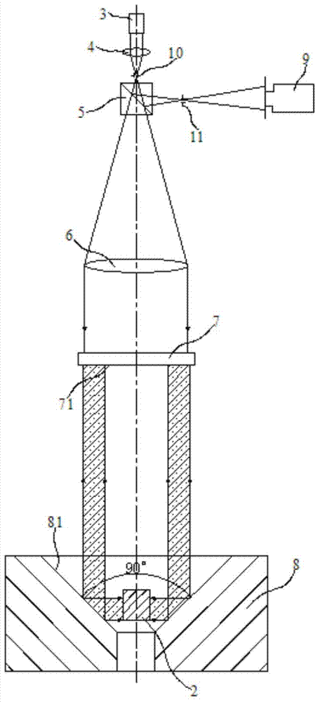
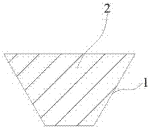
[0025] Embodiment 1: an optical interferometer for detecting the outer surface of a cylinder, the outer surface 1 is positioned at the outside along the circumference of the cylinder 2, including a laser 3, a focusing convex lens 4, a beam splitter 5, and a collimator as an objective lens Convex lens 6, standard flat crystal 7 and annular bevel reflector 8, described condensing convex lens 4 is positioned between laser 3 and collimating convex lens 6 and the focal point of condensing convex lens 4 coincides with the focal point of collimating convex lens 6; The mirror 5 is located between the condensing convex lens 4 and the collimating convex lens 6, and is used to divide the light from the collimating convex lens 6 into a first light beam and a second light beam; the standard flat crystal 7 is located between the collimating convex lens 6 and the beam splitter 5 on the opposite side, the surface opposite to the standard flat crystal 7 and the collimating convex lens 6 is a st...

Embodiment 2

[0032] Embodiment 2: an optical interferometer for detecting the outer surface of a cylinder, the outer surface 1 is positioned at the outside along the circumference of the cylinder 2, including a laser 3, a focusing convex lens 4, a beam splitter 5, and a collimator as an objective lens Convex lens 6, standard flat crystal 7 and annular bevel reflector 8, described condensing convex lens 4 is positioned between laser 3 and collimating convex lens 6 and the focal point of condensing convex lens 4 coincides with the focal point of collimating convex lens 6; The mirror 5 is located between the condensing convex lens 4 and the collimating convex lens 6, and is used to divide the light from the collimating convex lens 6 into a first light beam and a second light beam; the standard flat crystal 7 is located between the collimating convex lens 6 and the beam splitter 5 on the opposite side, the surface opposite to the standard flat crystal 7 and the collimating convex lens 6 is a st...


PUM


Abstract

The invention discloses an optical interferometer used for detecting the outer surface of a cylinder. A condensation convex lens is located between a laser and a collimation convex lens, and the focus of the condensation convex lens and the focus of the collimation convex lens coincide; a beam splitter located between the condensation convex lens and the collimation convex lens is used for dividing light of an auto-collimation convex lens into a first light beam and a second light beam; a standard optical flat is located on one side, back to the beam splitter, of the collimation convex lens, and the surface, back to the collimation convex lens, of the standard optical flat is a standard surface; an annular reflection inclined surface located at the center of an annular inclined surface reflector is arranged on the inner side in the circumferential direction of the annular inclined surface reflector, the to-be-detected cylinder is located in the annular inclined surface reflector, a rotary shaft of the annular inclined surface reflector, the axis of the cylinder and the axis of the optical flat coincide, and the annular reflection inclined surface of the annular inclined surface reflector and the outer surface of the cylinder are placed oppositely. According to the optical interferometer, the feature information of the inner surface of the whole stereoscopic cylinder can be obtained at a time, and test efficiency, accuracy and reliability are also greatly improved.

Description

technical field [0001] The invention relates to an optical detection device, in particular to an optical interferometer for detecting the outer surface of a cylinder. Background technique [0002] Optical interference technology is one of the most precise and effective testing technologies in modern times. It integrates the latest contemporary technologies, widely adopts the latest achievements in computer technology, laser technology, electronic technology, semiconductor technology and other fields, and can quickly and accurately complete the inspection of optical parts. Check with the system. In today's optical workshop, from the design, processing and inspection of optical parts to the assembly, calibration and testing of optical systems, interferometers have become an essential testing and inspection device that is easy to operate, reliable, high-precision, and intelligent. It plays an inestimable role in the mass production and inspection of optical components and syst...

Claims


Application Information

Patent Timeline
IPC IPC(8): G01B9/02G01B11/24
Inventor 韩森李雪园
Owner 苏州慧利仪器有限责任公司
Why Eureka
Try Eureka