Inverter welding machine with PFC (Positive Feedback Circuit) function

A technology of inverter welding machine and rectifier circuit, which is applied in the direction of output power conversion device, conversion of DC power input to DC power output, energy industry, etc., which can solve the problems of large power grid damage and low power utilization rate, and achieve energy saving energy, avoid harmonic interference, and improve the effect of power utilization

Inactive Publication Date: 2014-03-05
SHANGHAI HUGONG ELECTRIC WELDING MACHINE MFG
View PDF0 Cites 1 Cited by
  • Summary
  • Abstract
  • Description
  • Claims
  • Application Information

AI Technical Summary

Problems solved by technology

The traditional inverter welding machine has a power factor of 0.6-

Method used


Image

  • Inverter welding machine with PFC (Positive Feedback Circuit) function

Examples


Embodiment Construction

[0017] Embodiments of the present invention are described in detail below:

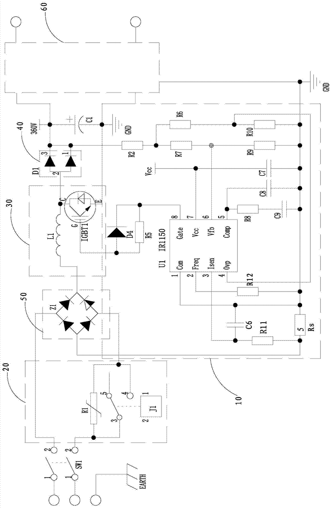
[0018] Such as figure 1 As shown, an inverter welding machine with PFC function includes an AC input switch SW1, a rectifier circuit 50, a boost circuit 30, a fast rectifier circuit 40, a filter circuit and an inverter circuit 60 connected in sequence, and the boost circuit 30 includes an inductor L and an insulated gate bipolar transistor IGBT, one end of the inductor L is connected to the positive output end of the rectifier circuit 50, the other end of the inductor L is connected to the collector of the IGBT, and the emitter of the IGBT is connected to the The negative output terminal of the rectification circuit 50 is connected, and a sampling resistor R is connected between the emitter of the IGBT and the negative output terminal of the rectification circuit 50. s , the sampling resistor R s A PFC control circuit is connected in parallel at both ends, and the PFC control circuit 10 is connected...


PUM


Abstract

The invention discloses an inverter welding machine with a PFC (Positive Feedback Circuit) function. The inverter welding machine comprises an alternating-current power input switch, a rectifying circuit, a booster circuit, a fast rectifying circuit, a filter circuit and an inverter circuit which are connected in sequence, wherein the booster circuit comprises an inductor and an IGBT (Insulated Gate Bipolar Translator), one end of the inductor is connected with a positive output end of the rectifying circuit; the other end of the inductor L is connected with a collector electrode of the IGBT; an emitter electrode of the IGBT is connected with a negative output end of the rectifying circuit; a sampling resistor Rs is connected between the emitter electrode of the IGBT and the negative output end of the rectifying circuit; PFC control circuits are in parallel connected at the two ends of the sampling resistor Rs; the PFC control circuits are respectively connected with a gate electrode of the IGBT and the fast rectifying circuit. The inverter welding machine disclosed by the invention can correct and follow voltage-current waveform by the PFC control circuits, so that harmonic interference generated when phases of current and voltage are inconsistent is avoided. Besides, the inverter welding machine disclosed by the invention can greatly improve utilization rate of electric energy, saves energy noises, and is low in noise.

Description


Claims


Application Information

Patent Timeline
Owner SHANGHAI HUGONG ELECTRIC WELDING MACHINE MFG
Why Eureka
Try Eureka