Method for designing corrugated steel sheet, and corrugated steel sheet pipe
A technology of corrugated steel plates, design methods, applied in the direction of pipes, rigid pipes, mining equipment, etc.
- Summary
- Abstract
- Description
- Claims
- Application Information
AI Technical Summary
Problems solved by technology
Method used
Image
Examples
Embodiment 1
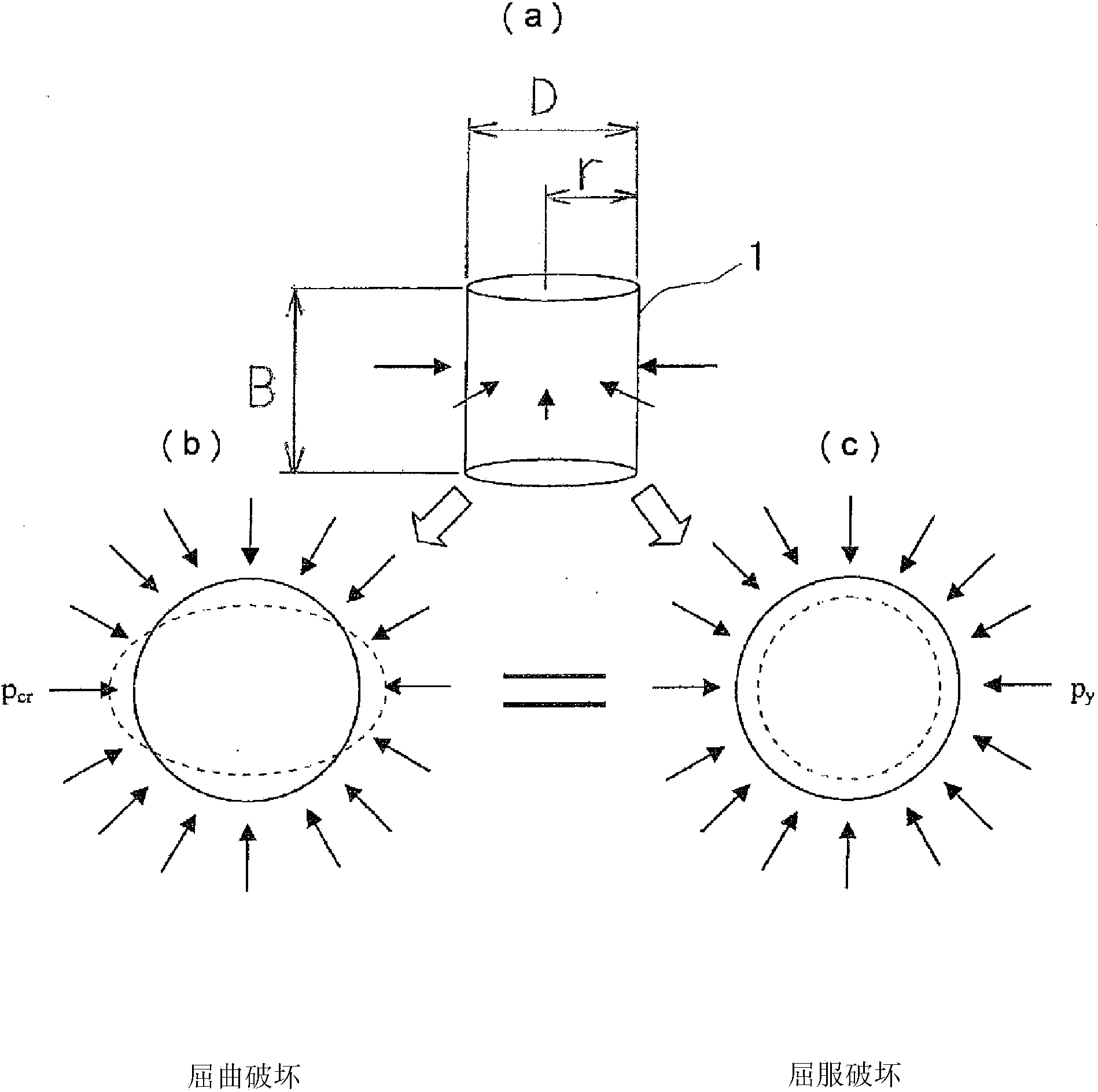
[0074] In the embodiment of the present invention, based on the premise that the outer surface of the corrugated steel pipe is subjected to uniform external pressure (this premise will be described later), the ring buckling corresponding pressure p when the corrugated steel pipe is buckled cr Corresponding pressure p to yield at yield y In an equal manner, set the wave shape of the corrugated steel plate.
[0075] if by figure 1 To explain this, there is a case where the corrugated steel pipe 1 receives a uniform external pressure (indicated by an arrow) on its outer surface in (a), and there is a case where the ring does not maintain a circular shape but buckles as shown by the dotted line in (b). The case where the ring buckles, and the case where the ring compresses and yields in the circumferential direction while maintaining a circular shape as shown by the dotted line in (c).
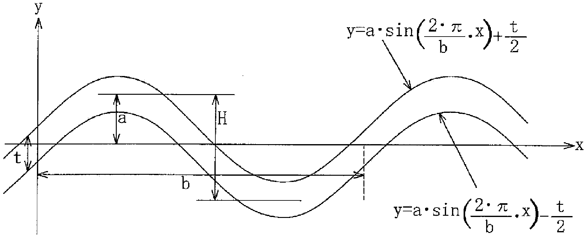
[0076] figure 2 Indicates the wave shape of a general corrugated steel plate used for cor...
Embodiment 2
[0150] When the relationship between the pipe diameter D and the wave depth H is set so as to lie on the relationship line obtained by the formula (8) or formula (10), the wave depth H is set in a non-stepwise manner corresponding to the size of the pipe diameter D, It is more complicated in manufacturing and construction in other aspects, and the cost increases, so it is more practical to make the depth H of the wave correspond to the diameter D of the pipe in stages.
[0151] For example Figure 7 As shown, the setting method of changing the depth H of the wave for every 2000mm of the pipe diameter D can be adopted.
[0152] In the case of step-by-step changes, yield failure, which is less prone to rapid failure, is more suitable as the failure form of the structure than buckling failure, which causes rapid failure. It is better to set in the range of "buckling load>yield load" (setting so as not to enter the range of "buckling load Figure 7 The phase relationship line in ...
Embodiment 3
[0165] In the above-mentioned embodiments, the description mainly assumes corrugated pipes, but the corrugated steel pipes targeted by the present invention are not limited to products with existing names such as corrugated pipes or liners, and can be applied to products that use corrugated steel plates. A tubular structure made of corrugated steel plates.
PUM
| Property | Measurement | Unit |
|---|---|---|
| Yield stress | aaaaa | aaaaa |
| Yield stress | aaaaa | aaaaa |
Abstract
Description
Claims
Application Information
 - R&D
- Intellectual Property
- Life Sciences
- Materials
- Tech Scout
- Unparalleled Data Quality
- Higher Quality Content
- 60% Fewer Hallucinations
Browse by: Latest US Patents, China's latest patents, Technical Efficacy Thesaurus, Application Domain, Technology Topic, Popular Technical Reports.
© 2025 PatSnap. All rights reserved.Legal|Privacy policy|Modern Slavery Act Transparency Statement|Sitemap|About US| Contact US: help@patsnap.com


