
Boot band

A technology of clamps and sleeves, applied in applications, couplings, connecting components, etc., can solve the problems of reduced rigidity, insufficient bending load resistance, and reduced bending load.

Active Publication Date: 2014-03-05
NHK SPRING CO LTD
View PDF7 Cites 2 Cited by
  • Summary
  • Abstract
  • Description
  • Claims
  • Application Information

AI Technical Summary

Problems solved by technology

However, as the thickness of the plate becomes thinner, the rigidity decreases, so the bending load during fastening decreases.
In this case, even with the anti-bending structure described in Patent Document 1, the bending load resistance cannot be sufficiently improved, and the occurrence of bending may not be prevented in some cases.

Method used


Image

  • Boot band
  • Boot band
  • Boot band

Examples


no. 1 approach )

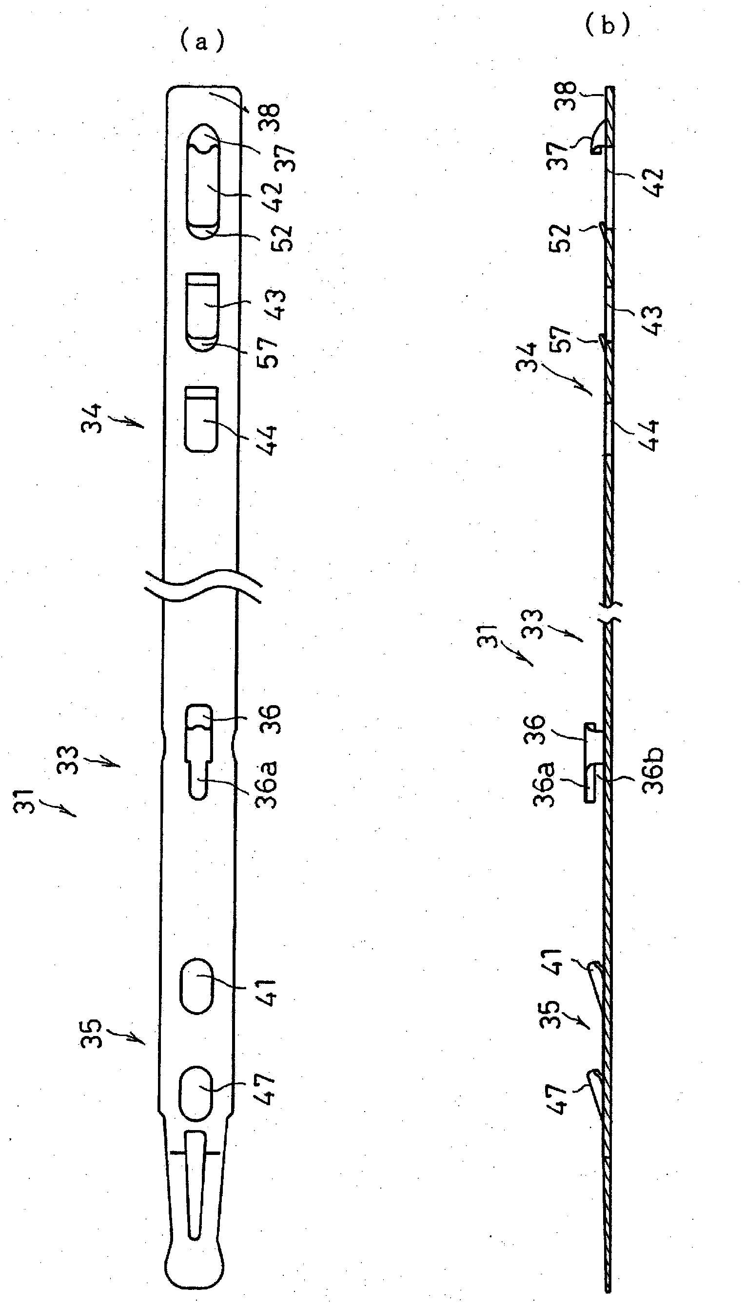
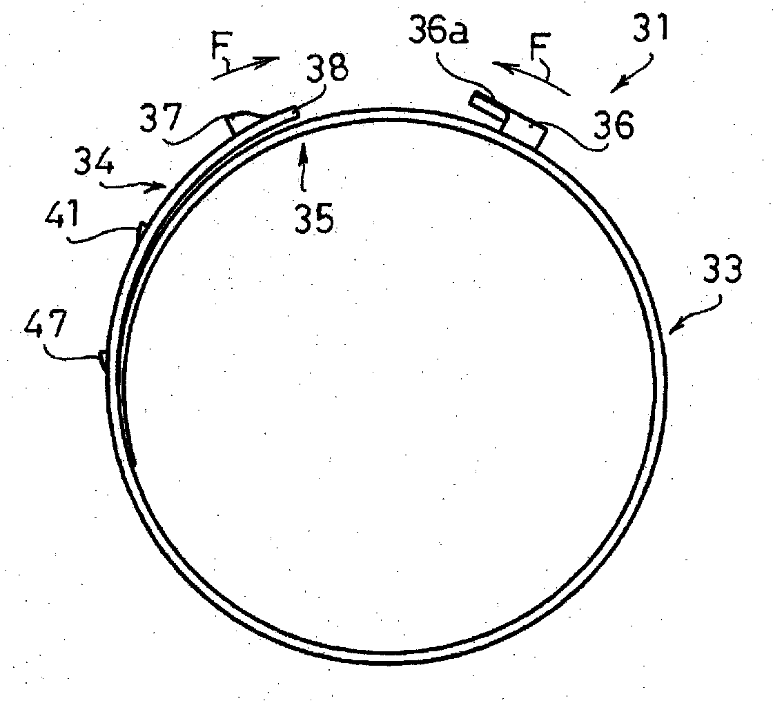
[0040] Figure 1 to Figure 7 The first embodiment of the present invention is shown. Such as Figure 1 ~ Figure 3 As shown, the sleeve collar 31 is formed from a collar body 33 constructed of sheet metal.

[0041] The clip main body 33 is formed into a strip shape by punching a thin metal plate, and is used for fastening fastened members (not shown) such as sleeves in a state of being wound from the strip shape into a ring shape. The ring-shaped clamp body 33 is formed with overlapping outer overlapping portions 34 and inner overlapping portions 35, and these overlapping portions 34, 35 pass through in the diameter-reducing direction ( figure 2 In the direction of the middle arrow F) pull each other (引き店せる) to fasten the fastened parts.

[0042] On the front end side of the outer overlapping portion 34 ( figure 1 The right end side in the center) is formed with a first tool claw 37 standing radially outward. A flat terminal portion 38 is formed on a free end at the fron...

no. 2 approach )

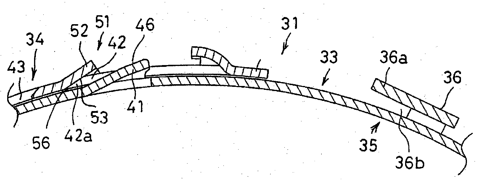
[0068] Figure 8 and Figure 9 A sleeve clip 31A according to a second embodiment of the present invention is shown. The difference from the first embodiment is that in the sleeve clip 31A, the guide unit 51 is the inner surface 55 of the rear end portion 42a opposite to the engaging claw 41 in the front end side engaging hole 42, and the inclined portion 53 is provided on the The inner surface 55 and other components are the same as those of the first embodiment.

[0069] In the ferrule clip 31A of this embodiment, with respect to the engaging claws 41 of the inner overlapping portion 35 , an engaging hole 42 on the front end side and a subsequent engaging hole 43 on the rear side are formed along the longitudinal direction of the outer overlapping portion 34 . The inclined portion 53 of the inner surface 55 of the front end engaging hole 42 is formed by press molding, coining, etc. so as to incline in the same direction as the rear surface 46 of the engaging claw 41 along ...


PUM


Abstract

Provided is a boot band capable of preventing the occurrence of buckling in the inner overlapping part. In the boot band (31), by applying a diameter-reducing tightening force on the band body (33) when an engaging tab (41) of the inner overlapping part (35) has entered a leading end engagement hole (42) of the outer overlapping part (34), the leading end engagement hole (42) rides over the engaging tab (41). Buckling is prevented by providing a guide means (51), which faces the engaging tab, at the area of the leading end engagement hole (42) opposite where the engaging tab (41) enters therein.

Description

technical field [0001] The present invention relates to a ferrule clip capable of fixing a fastened member to a target member by fastening a fastened member such as a ferrule made of rubber or resin. Background technique [0002] The bushing clip can be used, for example, in a constant velocity joint (joint) that transmits driving force of an engine from a drive shaft to a driven shaft. In the constant velocity joint, the power transmission part is covered with a corrugated sleeve, and lubricating oil is sealed inside the sleeve. The bushing clamp is wound around the outer circumference of both ends of the bushing and reduced in diameter to fasten the bushing and prevent lubricating oil from leaking from the inside of the bushing. In such a sleeve clip, a pair of tool claws that can be fastened by a fastening tool is provided, and a tightening force in a diameter-reducing direction acts through the pair of tool claws. [0003] Figure 12 A conventional bushing clamp 1 is s...

Claims


Application Information

Patent Timeline
Patent Type & Authority Applications(China)
IPC IPC(8): F16B2/08F16D3/84
CPCF16D2003/22316F16J15/3464F16B2/08F16J3/042Y10T24/14F16D3/845
Inventor 荻野隆司池田博
Owner NHK SPRING CO LTD
Learn More