Eureka AIR delivers breakthrough ideas for toughest innovation challenges, trusted by R&D personnel around the world.

Valve fatigue-life testing device

A testing device and fatigue life technology, applied in the direction of heart valve, etc., can solve problems such as difficulty in adjusting the pressure waveform, and achieve the effect of simple adjustment of the pressure waveform

Active Publication Date: 2014-03-12
上海心瓣测试设备有限公司
View PDF9 Cites 9 Cited by
  • Summary
  • Abstract
  • Description
  • Claims
  • Application Information

AI Technical Summary

Problems solved by technology

Although the device can complete the in vitro simulation test, it still has the following disadvantages: (1) The heart valve of the device is fixed on the valve holder connected to the linear motor, that is, the linear motor drives the valve holder to move up and down, thereby The valve moves up and down with the retainer to realize the opening and closing of the valve
(2) Since the adjustment of the afterload (the load received during the contraction process) is completely realized by mechanical and hydrodynamic means, and the transvalvular pressure depends on the adjustment of the afterload, it is difficult to adjust the pressure waveform

Method used


Image

  • Valve fatigue-life testing device
  • Valve fatigue-life testing device
  • Valve fatigue-life testing device

Examples


Embodiment Construction

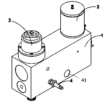
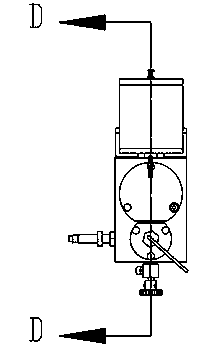
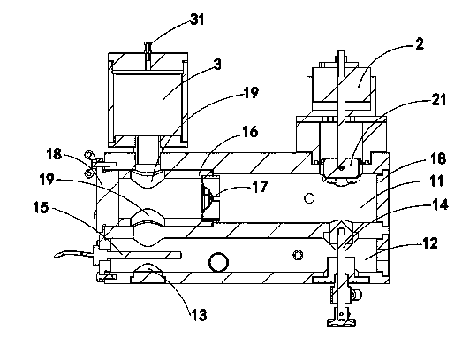
[0023] The present invention discloses a valve fatigue life testing device, and the present invention will be further described below in conjunction with an artificial heart valve. Such as Figure 1 to Figure 3 As shown, at least one module assembly is included, and the module assembly includes a body 1 . An opening 13 is provided on the bottom side of the body 1, and an outlet valve 41 is provided on the side of the body for releasing the test liquid in the device. A linear motor 2 is mounted on one side of the top of the body, and a piston 21 with a rolling diaphragm is connected to the shaft of the linear motor 2 , and the piston 21 is inserted into the body 1 .

[0024] The other side of the top of the body 1 is provided with a liquid container 3, the liquid container 3 communicates with the body 1, and the top of the liquid container 3 is provided with an open cover 31;

[0025] The interior of the body 1 is mainly composed of upper and lower flow passages that communic...


PUM


Abstract

The invention provides a valve fatigue-life testing device. The valve fatigue-life testing device comprises a body at least, wherein the body is composed of an upper channel and a lower channel which is communicated with the upper channel, one side of the bottom of the body is provided with an opening, a linear motor is arranged on one side of the top of the body, a liquid container which is communicated with the body is arranged on the other side of the top of the body, and a cover is arranged at the top of the liquid container. A damper is arranged at one end of the lower channel and under the linear motor, and a temperature sensor is arranged at the other end of the lower channel. The upper channel of the body further comprises a valve fixer provided with a through hole, wherein the valve fixer is horizontally placed inside the upper channel of the body and arranged below the liquid container. A shaft of the linear motor is connected with a piston provided with a rolling membrane, and the piston is arranged inside the body in a stretching mode. The linear motor of the valve fatigue-life testing device enables loads to be directly applied to test liquid in a waveform mode under current control and to be transmitted to a test valve or other test pieces according to the Pascal law, and high-frequency oscillation signals in the test liquid are filtered through the liquid container. All test indexes can meet relevant national standards for artificial cardiac valves which are cardiovascular implants, and the final testing result is accurate and reliable.

Description

technical field [0001] The invention relates to a fatigue life testing device, in particular to a fatigue life testing device for artificial heart valves and artificial cardiovascular related products. Background technique [0002] Heart valvular disease is one of the major heart diseases at present, and has various etiologies such as rheumatic, degenerative, and congenital, and the only treatment for most patients with valvular disease is artificial heart valve replacement. The quality of the valve is directly related to the safety of the patient, so it is necessary to test and understand the various performance indicators of the valve. Evaluation and comparison and mechanical properties are mainly realized by in vitro simulation experimental devices. Among them, the in vitro test of artificial heart valve fatigue life is an important means to evaluate the design, and it is also a prerequisite for clinical trials. [0003] For example, the Chinese patent proposed by the a...

Claims


Application Information

Patent Timeline
Patent Type & Authority Applications(China)
IPC IPC(8): A61F2/24
Inventor 李守彦
Owner 上海心瓣测试设备有限公司
Why Eureka
Eureka Blog
Learn More