Welding tool

A technology for welding tooling and welding parts, applied in welding equipment, auxiliary welding equipment, welding/cutting auxiliary equipment, etc. The effect of employee labor intensity

Active Publication Date: 2014-03-12
GREE ELECTRIC APPLIANCES INC
View PDF7 Cites 20 Cited by
  • Summary
  • Abstract
  • Description
  • Claims
  • Application Information

AI Technical Summary

Problems solved by technology

[0003] The purpose of the present invention is to provide a welding tool to solve the technical problem of high labor intensity for employees walking back and forth between two stations

Method used


Image

  • Welding tool

Examples


Embodiment Construction

[0019] The embodiments of the present invention will be described in detail below with reference to the accompanying drawings, but the present invention can be implemented in many different ways defined and covered by the claims.

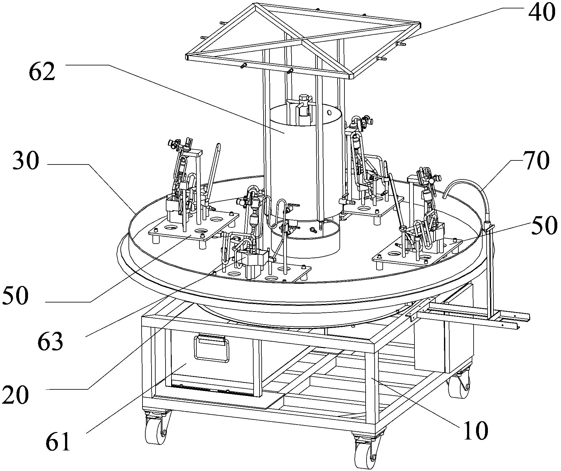
[0020] see figure 1 , according to the welding tooling of the present invention, comprises support 10; Chassis 20, is arranged on the support 10; Rotatable turntable 30, is rotatably arranged on the chassis 20; 30 rotates and communicates with the parts to be welded; multiple positioning structures 50 of the parts to be welded are uniformly arranged at multiple circumferential positions of the turntable 30; it also includes an automatic water spray mechanism for cooling the welded parts, an automatic water spray mechanism and a bracket 10 phase connections. In the embodiment of the present invention, the part to be welded is a four-way valve body. Preferably, the welding tool has four stations, namely four positioning structures 50 for the part to ...


PUM


Abstract

The invention provides a welding tool. The welding tool comprises a support, a chassis, a rotating disc capable of rotating, a nitrogen distributing system, a plurality of positioning structures for workpieces to be welded and an automatic water spraying mechanism, wherein the chassis is arranged on the support; the rotating disc is rotably arranged on the chassis; the nitrogen distributing system is arranged at the center of the rotating disc, rotates along with the rotating disc and is communicated with the workpieces to be welded; the positioning mechanisms are evenly arranged on a plurality of circumferential positions of the rotating disc; the automatic water spraying mechanism is used for cooling the welded workpieces and connected with the support. Because the welding positioning mechanisms are arranged on the rotating disc and the rotating disc automatically rotates, an existing standing and back-and-forth walking type welding mode is replaced, and labor intensity of workers is reduced; working efficiency of the workers is greatly improved, and welding quality and efficiency are improved.

Description

technical field [0001] The invention relates to the field of welding, in particular to a welding tool. Background technique [0002] The way of welding four-way valve components in the prior art is standing and walking back and forth welding, and two welding posts are operated by three people, one of whom is piping, one is welding, and one is unloading. The welder walks back and forth between the two stations for welding, the labor intensity of the employees is high, and the welding of the four-way valve needs to be filled with nitrogen, the body of the four-way valve needs to be soaked in water for protection, and it needs to be sprayed with water to remove scale after welding, etc., while the existing welding It is difficult to meet various requirements. Contents of the invention [0003] The purpose of the present invention is to provide a welding tool to solve the technical problem of high labor intensity for employees walking back and forth between two workstations. ...

Claims


Application Information

Patent Timeline
Patent Type & Authority Applications(China)
IPC IPC(8): B23K37/00B23K37/047
CPCB23K37/00B23K37/003B23K37/0426B23K37/0461B23K37/047
Inventor 侯纪波
Owner GREE ELECTRIC APPLIANCES INC
Why Eureka
Try Eureka