
Bridge head jumping prevention structure based on concrete composite pavement and its laying method

A composite road and bridge head jumping technology is applied to the bridge head jump prevention structure based on concrete composite road and its laying field, which can solve the problems of shortening the service life of the vehicle, increasing the vibration and damage of the vehicle, and improving the bearing capacity of the foundation. Insufficient, reduce differential settlement deformation, enhance the effect of bearing capacity and strength

Inactive Publication Date: 2016-05-18
CHANGAN UNIV
View PDF6 Cites 2 Cited by
  • Summary
  • Abstract
  • Description
  • Claims
  • Application Information

AI Technical Summary

Problems solved by technology

Jumping makes the driver and passengers feel uncomfortable, unhappy and easily fatigued, and the goods carried are easily damaged; serious jumping will cause traffic accidents such as rollover and rear-end collision, threatening the safety of people, vehicles and objects, and causing loss of life and property; ② Difference Settlement causes impact loads to be generated when vehicles pass through structures such as bridges and culverts, and its horizontal and vertical impact forces will cause further damage to road surfaces, roadbeds, and bridge structures, thereby increasing maintenance costs and management difficulties, and reducing road performance; ③ Jumping at the bridge head will cause great damage to the vehicle, increase the vibration of the vehicle, aggravate the wear of parts and tires and the fuel consumption of driving, shorten the service life of the vehicle, and increase the transportation cost
[0005] At present, bridge head straps are set up on ordinary road sections to slow down the generation of differential settlement, but the differential settlement at both ends of the short-circuit foundation is larger than that of ordinary road sections, and the mitigation ability of bridge head straps is limited
At the same time, when the subgrade is too short, it is impossible to set up the board due to the length limit

Method used


Image

  • Bridge head jumping prevention structure based on concrete composite pavement and its laying method

Examples


Embodiment Construction

[0025] The invention will be described in further detail below in conjunction with the accompanying drawings.

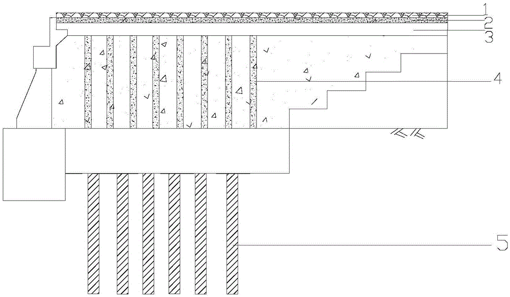
[0026] see figure 1 , the bridge head vehicle jumping prevention structure based on the concrete composite road surface includes a composite foundation 5 of lime-soil compaction piles, and a composite roadbed 4 with internally driven cement piles is laid on the composite foundation 5 of lime-soil compaction piles. The cement piles are of equal height and equidistant For setting, a base layer 3 is laid on the composite subgrade 4, an oblique prestressed concrete layer 2 is laid on the base layer 3, and an asphalt layer 1 is laid on the oblique prestressed concrete layer 2.

[0027] In the present invention, the composite roadbed 4 is a roadbed in which cement piles are driven in, wherein the cement piles are arranged at equal heights and at equal distances, the pile diameter of the cement piles is 400mm, the pile distance is 1.5m, and the pile length is 6m.

[0028] ...


PUM


Abstract

The invention discloses a bridgehead vehicle bumping prevention structure based on a concrete composite pavement and a laying method thereof. The bridgehead vehicle bumping prevention structure comprises a lime-soil compaction pile composite foundation, wherein a composite foundation, in which concrete piles are built, is laid on the composite foundation; the concrete piles are in equal height and equal distance; a base layer is laid on the composite foundation; an oblique prestressed concrete layer is laid on the base layer; an asphalt layer is laid on the oblique prestressed concrete layer. According to the structure, the foundation has enough bearing force and is filled with the concrete piles, so that the bearing force of the foundation can be further improved, and uneven settlement of the foundation is alleviated. According to the method, the construction process quality is controllable, continuous operation is realized, the problems of bridgehead vehicle bumping accidents, early pavement damage and the like due to uneven settlement of the back of a bridge abutment can be effectively reduced, the bridgehead vehicle bumping accidents troubling the highway management department for many years can be avoided, the service performance of the pavement can be greatly improved, the service life of the pavement is obviously prolonged, and the bridgehead vehicle bumping prevention structure has obvious economic benefits.

Description

technical field [0001] The invention belongs to the technical field of prevention and treatment of vehicle jumping at the bridge head of road engineering, and in particular relates to a structure for preventing vehicle jumping at the bridge head based on a concrete composite road surface and a laying method thereof. Background technique [0002] According to incomplete statistics, for expressways, there are only 3 passages and culverts per kilometer on average, and even 4-5 for some lines. Judging from the operating conditions of the high-grade highways that have been put into use, especially the expressways, there are some unsatisfactory aspects, especially the phenomenon of vehicle jumping at the bridge head is common in the backfill of the backfill of these structures. The so-called bridge head jumping refers to the continuous settlement of bridges, passages, culverts and other structures themselves and the backfill of the abutment due to the driving load and self-weight....

Claims


Application Information

Patent Timeline
Patent Type & Authority Patents(China)
IPC IPC(8): E01C3/02E01D19/12E01D21/00
Inventor 张东省郑木莲王帅王涛屈仆
Owner CHANGAN UNIV
Learn More