Electromagnetic anti-wax device

A wax preventer and electromagnetic technology, applied in instruments, adjusting electrical variables, isolation devices, etc., can solve the problems of weak electromagnetic field and inability to prevent wax, and achieve the effects of increasing production, simple installation, and prolonging wax removal cycle.

Inactive Publication Date: 2014-03-12
YINCHUAN GUANGYIDA ENERGY SAVING TECH
View PDF4 Cites 3 Cited by
  • Summary
  • Abstract
  • Description
  • Claims
  • Application Information

AI Technical Summary

Problems solved by technology

When the frequency increases to 20KHz-30KHz, the current drops sharply, only tens of milliamperes, and the energy of the electromagnetic field is closely related to the current. At this time, the current is weak, and the electromagnetic field generated is also very weak, which cannot prevent wax. Effect

Method used


Image

  • Electromagnetic anti-wax device
  • Electromagnetic anti-wax device
  • Electromagnetic anti-wax device

Examples


Embodiment 1

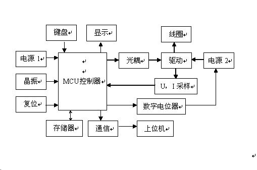
[0020] 1. Dual power supply design (microprocessor power supply voltage 5v, load voltage changes with operating frequency), see Figure three .

[0021] 2. When the current in the load coil is working at 20KHz-30KHz, the peak-to-peak current output reaches 10A.

[0022] 3. In order to improve the working efficiency of the wax preventer, it adopts multi-module design and installation

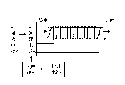
[0023] The present invention uses the MCU as the core component to generate a square wave signal whose frequency can be changed, and then outputs the square wave signal to the H-bridge drive circuit via the high-voltage side suspension drive IRZI10 (with optical isolation and electromagnetic isolation). Finally, a variable frequency square wave signal with a large current output is sent to the coil.

[0024] Power supply 1 is the power supply of the MCU, and supplies power to the attached devices at the same time;

[0025] Power supply 2 is to supply power to the H-bridge drive circuit to incr...

Embodiment 2

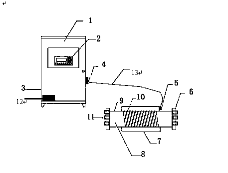
[0029] Electromagnetic wax preventer, its composition includes main machine part 1 and auxiliary machine part 2, described electromagnetic wax preventer, auxiliary machine is made of PPR or the middle outer part of iron-based pipe 9 winding 1.5mm 2 ~3.5mm 2 The double-core cable 10 is connected to the terminal 5 or the aviation plug at both ends, the terminal is fixed on the protective shell 7, and the two ends are welded with iron base or PPR flange 6, which can be connected through the screw 11 on the flange and the oil pipe. Flange connection.

Embodiment 3

[0031] Above-mentioned electromagnetic wax preventer, main engine 1 is made up of display screen 2, and power switch is arranged on said display screen 2, keyboard, working state indicator lamp, display screen, is connected with auxiliary aircraft aviation socket 5 by aviation socket 4, is connected to cable 12 ; The host is connected to the power supply 13 .


PUM


Abstract

During crude oil exploitation and gathering and transportation, wax precipitation prevention or wax removal of an oil flowing channel is necessary for normal production of an oil field. At present, methods for removing wax mainly comprise the heating wax removing method, the mechanical wax removing method, the chemical agent wax removing method, the hot water and light oil pipeline washing method and the like, all the methods are great in limitation, a large number of manpower and material resources are needed, cost is high, the labor intensity is high, a large amount of energy is consumed, and the effective period is short. A novel electromagnetic anti-wax device is based on the electromagnetic anti-wax technique and is mainly composed of a main machine and an auxiliary machine, wherein a controller is arranged in the main machine, a pulse signal with a frequency changing continuously within a certain scanning cycle can be generated, the amplified pulse signal is transmitted to the auxiliary machine through bridge type power amplification and a transmission cable, the current of a load coil is kept unchanged through feedback control, the auxiliary machine is installed on an oil delivery pipeline, and oil is magnetized by flowing through the auxiliary machine. The electromagnetic anti-wax device is good in anti-wax effect, adaptable to various oil fields and oil qualities and low in energy consumption, and energy is saved and the environment is protected due to the adoption of a purely physical method.

Description

technical field [0001] The invention relates to an electromagnetic wax preventer for preventing wax in an oil field. Background technique [0002] Most of the crude oil produced in my country is paraffin-based crude oil. According to statistics, crude oil with a mass fraction of wax exceeding 10% accounts for almost 90% of all crude oil produced, and the mass fraction of most crude oil waxes is above 20%, and some are even as high as 40% to 50%. Unproduced paraffin-based crude oil generally does not precipitate wax under formation conditions, but in the process of oilfield development, crude oil flows from the oil layer to the bottom of the well, and then flows from the bottom of the well to the surface. During the production process, the pressure and temperature of the crude oil continue to drop. Waxes may be precipitated in crude oil. If the wax precipitates from the crude oil, it will block the oil flow channel and deposit on the tubing wall and surface equipment, reduc...

Claims


Application Information

Patent Timeline
Patent Type & Authority Applications(China)
IPC IPC(8): E21B36/00G05F1/66
Inventor 何军吴立春
Owner YINCHUAN GUANGYIDA ENERGY SAVING TECH
Why Eureka
Try Eureka