
Stirling heat engine based on liquid radioactive waste concentrates

A technology for radioactive waste and concentrate, which is applied in the direction of hot gas variable volume engine devices, mechanical equipment, machines/engines, etc., can solve the problems of unstable heat source, unstable working performance of Stirling heat engine, low working efficiency, etc. Stable working performance, high working efficiency and stable heat source

Active Publication Date: 2014-03-12
斯特林威索AB
View PDF8 Cites 2 Cited by
  • Summary
  • Abstract
  • Description
  • Claims
  • Application Information

AI Technical Summary

Problems solved by technology

[0004] In order to overcome the instability of the heat source in the Stirling heat engine in the prior art, resulting in unstable working performance and low working efficiency of the Stirling heat engine, the present invention provides a stable heat source, stable working performance and high working efficiency based on Stirling heat engine for liquid radioactive waste concentrates

Method used


Image

  • Stirling heat engine based on liquid radioactive waste concentrates
  • Stirling heat engine based on liquid radioactive waste concentrates
  • Stirling heat engine based on liquid radioactive waste concentrates

Examples


Embodiment Construction

[0019] The present invention will be further described below in conjunction with accompanying drawing and specific embodiment:

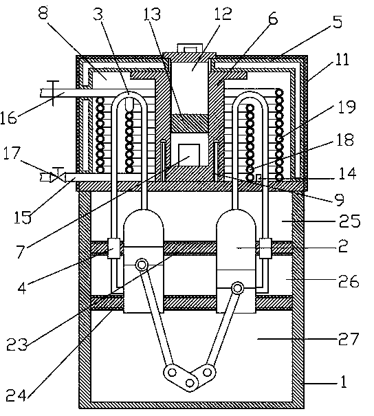
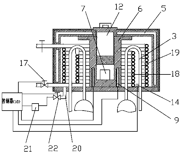
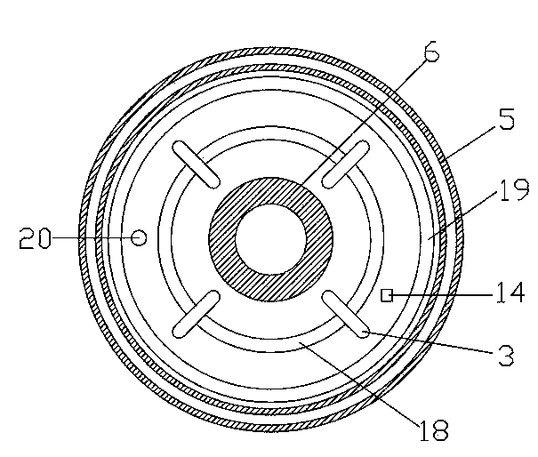
[0020] Such as figure 1 A Stirling heat engine based on liquid radioactive waste concentrate is shown, including a Stirling heat base 1, the Stirling heat base has a columnar structure, and four sealed cylinders 2 are arranged in the Stirling heat base, The piston rod in the cylinder protrudes from the lower end of the cylinder and is connected with the crank connecting rod mechanism. A U-shaped air pipe 3 is connected to the cylinder 2. A heat exchanger 4 is arranged on the U-shaped air pipe. One end of the U-shaped air pipe is connected to the upper end of the cylinder. The hot end of the U-shaped air pipe is connected to the cold end of the lower end of the cylinder. The upper end of the Stirling heat base 1 is provided with a sealed box body 5. The side wall of the box body 5 is a double-layer side wall. The cavity between the walls is in a ...


PUM


Abstract

The invention discloses a Stirling heat engine based on liquid radioactive waste concentrates. The Stirling heat engine based on liquid radioactive waste concentrates comprises a Stirling heat engine base. Multiple sealed air cylinders are arranged in the Stirling heat engine base. The outer ends of piston rods in the air cylinders are connected with a crank-link mechanism. U-shaped air pipes are connected to the air cylinders and heat exchangers are arranged on the U-shaped air pipes. One ends of the U-shaped air pipes are communicated with the hot ends of the upper ends of the air cylinders. The other ends of the U-shaped air pipes are communicated with the cold ends of the lower ends of the air cylinders. A sealed box body is arranged at the upper end of the Stirling heat engine base. A material storage tank is arranged in the middle of the box body and liquid radioactive waste concentrates are contained in the material storage tank. The material storage tank and the inner wall of the box body form an annular cavity. The bottoms of the U-shaped air pipes penetrate into the annular cavity and a pair of electronic poles is arranged on the two sides of the material storage tank. A controller is arranged outside the box body and the electronic poles are connected with the controller through guide wires. Thus, the Stirling heat engine based on liquid radioactive waste concentrates has the advantages of being stable in heat source, stable in working performance and high in working efficiency.

Description

technical field [0001] The invention relates to the technical field of Stirling heat engines, in particular to a Stirling heat engine based on liquid radioactive waste concentrate. Background technique [0002] The Stirling engine is a unique heat engine, because the theoretical efficiency is almost equal to the theoretical maximum efficiency, called the Carnot cycle efficiency, so the Stirling engine has a wide range of applications in new energy power generation and military industry. The Stirling engine generates power by expanding the gas when it is heated and compressing it when it is cold. The air-conditioning chamber is cooled, and this cycle process is repeated repeatedly. The outer end of the piston handle is connected to the crank linkage mechanism, thereby driving the three-phase generator to rotate, and converting mechanical energy into electrical energy. The external heat source of the common Stirling heat engine is usually heated by fuel combustion or solar he...

Claims


Application Information

Patent Timeline
Patent Type & Authority Applications(China)
IPC IPC(8): F02G1/043F02G1/055F02G1/053
Inventor 万斌
Owner 斯特林威索AB
Learn More