Eureka AIR delivers breakthrough ideas for toughest innovation challenges, trusted by R&D personnel around the world.

Vibration damper

A shock absorber and height adjustment technology, applied in the direction of shock absorbers, shock absorbers, springs/shock absorbers, etc., can solve problems such as stuck, loose connecting bolts, and spinning, and achieve the effect of preventing loose connections

Active Publication Date: 2014-03-12
ZHUZHOU TIMES NEW MATERIALS TECH
View PDF5 Cites 18 Cited by
  • Summary
  • Abstract
  • Description
  • Claims
  • Application Information

AI Technical Summary

Problems solved by technology

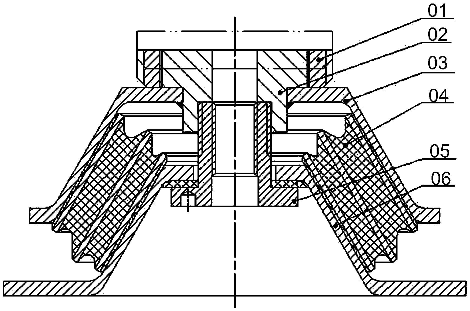
[0004] However, when adjusting the height of the shock absorber, the height adjustment nut 01 rotates up, and there is a gap between the adjustment nut 01 and the upper shell 03. When the generator is working, the vibration will cause the height adjustment nut 01 to shake on the nut platform 02. A long time will lead to loosening of the connecting bolts between the shock absorber and the generator, which will affect the safety of the unit
[0005] In addition, there are also problems in the installation and height adjustment process of the shock absorber. Due to individual differences, the friction between the elastic rubber 04 and the metal parts varies greatly during the installation of the shock absorber. When tightening the connecting bolts of the shock absorber and the generator , there will be a spinning phenomenon between the upper shell 03 and the lower support plate 06
During the height adjustment process of the shock absorber, due to human negligence, the height adjustment nut 01 was adjusted too high, so that the number of threads connected between the height adjustment nut 01 and the nut platform 02 was too small, resulting in the shock absorber in the working process. Thread deformation and jamming occur in the middle, and the height cannot be adjusted
[0006] To sum up, how to prevent the shock absorber from loosening the connection between the shock absorber and the equipment caused by the shaking during the work has become an urgent problem to be solved by those skilled in the art

Method used


Image

  • Vibration damper
  • Vibration damper
  • Vibration damper

Examples


Embodiment Construction

[0035] The core of the present invention is to provide a shock absorber, which prevents the shock absorber from shaking during operation, thereby preventing the loose connection between the shock absorber and the damped equipment caused by long-term shaking.

[0036] The following will clearly and completely describe the technical solutions in the embodiments of the present invention with reference to the accompanying drawings in the embodiments of the present invention. Obviously, the described embodiments are only part of the embodiments of the present invention, not all of them. Based on the embodiments of the present invention, all other embodiments obtained by persons of ordinary skill in the art without making creative efforts fall within the protection scope of the present invention.

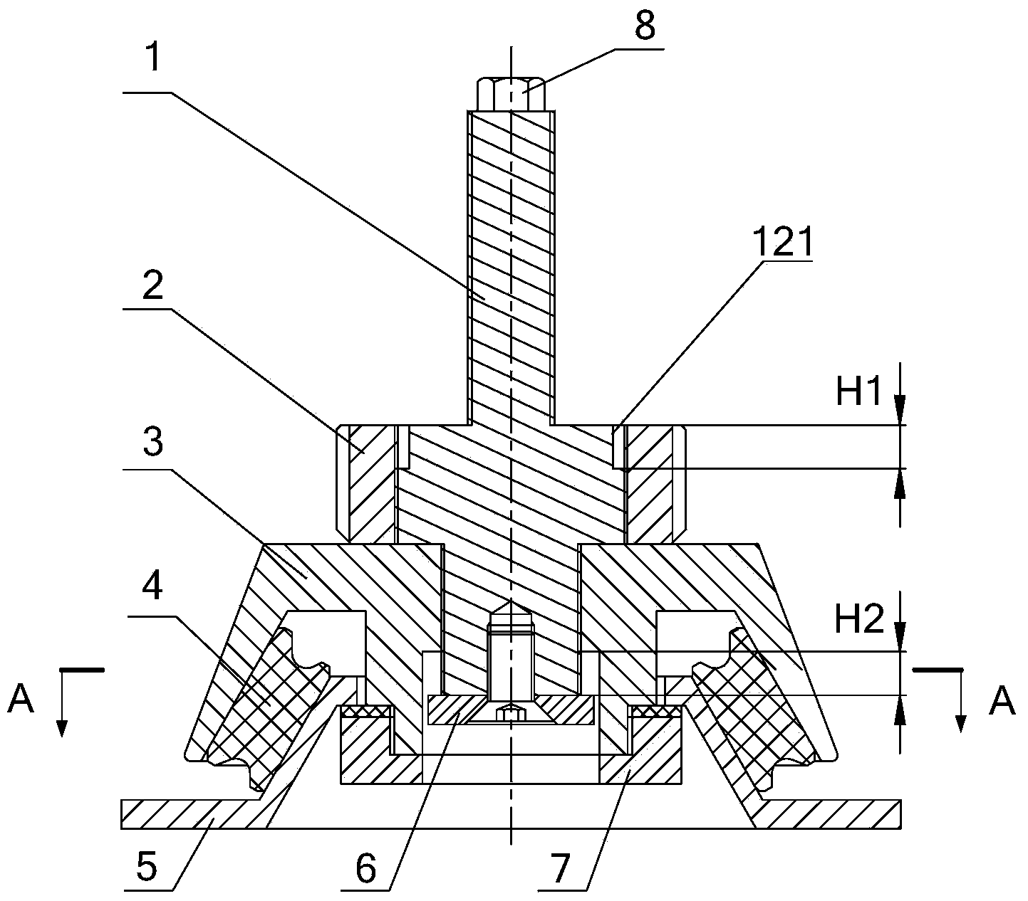
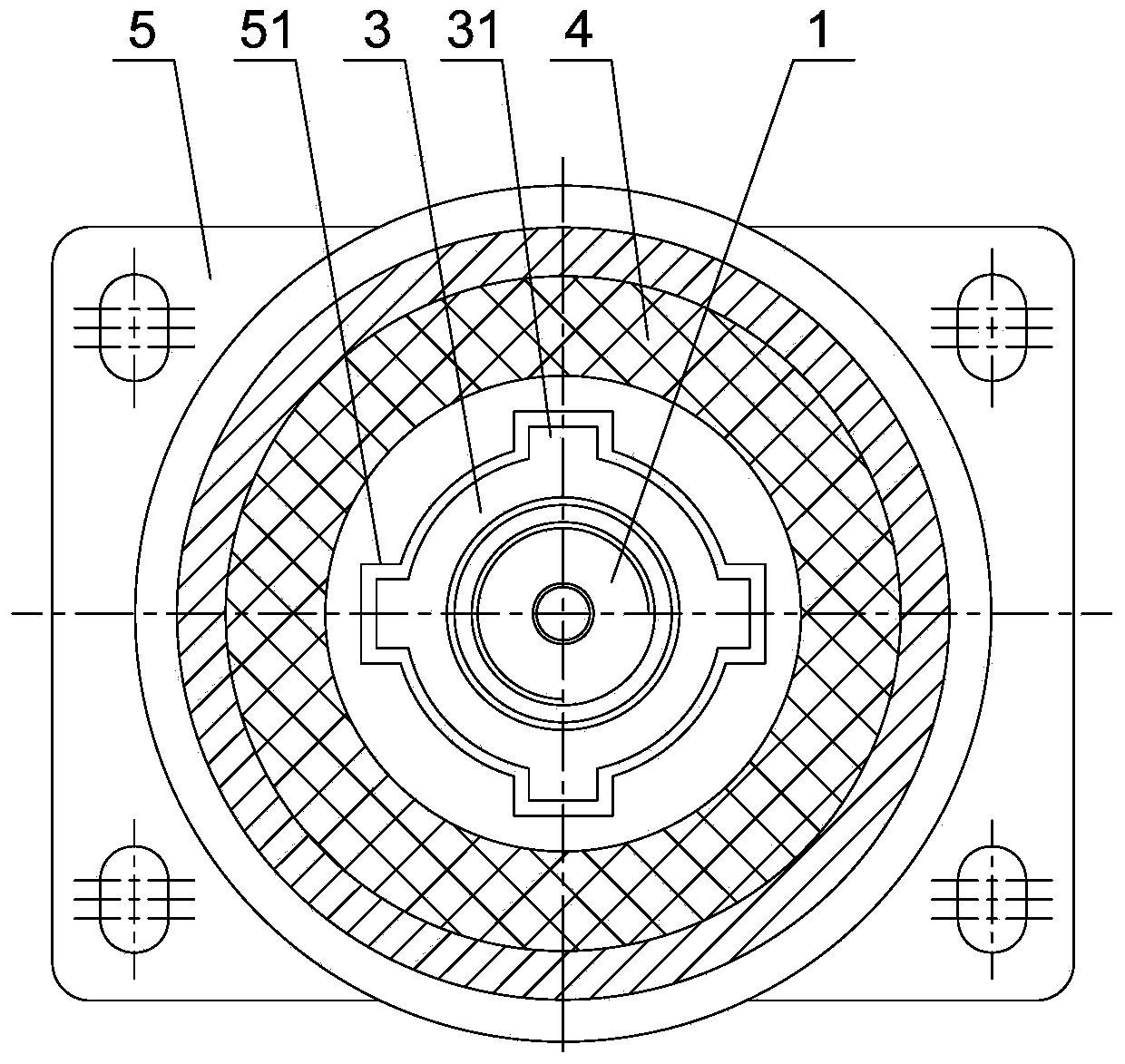
[0037] Please refer to Figure 2-Figure 7 , figure 2 A structural schematic diagram of a shock absorber provided by an embodiment of the present invention; image 3 for figure 2 A-A ...


PUM


Abstract

The invention discloses a vibration damper, which comprises an upper shell, wherein a height regulating threaded hole is formed in the center of the upper shell. The vibration damper also comprises a height regulating bolt and a locking nut which is tightly pressed against the upper end face of the upper shell, wherein the height regulating bolt comprises a first connecting section fixed on vibration-damped equipment, a second connecting section in threaded connection with the locking nut in a matched way and a third connecting section in threaded connection with the height regulating threaded hole in the matched way. According to the vibration damper, the height regulating bolt and the locking nut are in threaded connection with the upper shell to form a structure for regulating the height of the vibration damper, and when the height is regulated, the height regulating bolt is regulated to a required height by virtue of matched rotation between the third connecting section and the height regulating threaded hole, and the locking nut is tightly pressed against the upper end face of the upper shell, thereby firmly positioning the height regulating bolt in the upper shell and prevent the height regulating bolt from swaying in the upper shell; therefore, the condition that connection between the vibration damper and the vibration-damped equipment is loosened under the swaying of the height regulating bolt is prevented.

Description

technical field [0001] The invention relates to the technical field of equipment vibration reduction, in particular to a vibration absorber. Background technique [0002] Many mechanical equipment will vibrate when they are working. Harmful vibration will not only damage the components of the equipment and affect the normal operation of the equipment, but also generate a lot of noise. Taking the generator in the wind turbine as an example, the generator will generate large vibration during operation, which will be transmitted to the main frame and generate large noise. In order to reduce the vibration of the generator, it is necessary to connect the generator and the main frame A shock absorber is arranged between the shock absorbers to block the transmission of vibration and reduce noise. [0003] Existing shock absorbers generally adopt a metal-rubber composite structure, and the specific structure is as follows: figure 1 As shown, it consists of height adjustment nut 01...

Claims


Application Information

Patent Timeline
Patent Type & Authority Applications(China)
IPC IPC(8): F16F7/00
Inventor 林胜岳涛倪黎胡伟辉陈健程海涛黄祖华谭虢
Owner ZHUZHOU TIMES NEW MATERIALS TECH
Why Eureka
Eureka Blog
Learn More