
Wireless temperature measuring device

A wireless temperature measurement and wireless signal technology, applied in the field of wireless temperature measurement devices, can solve the problems of low reliability, low security, no intelligent alarm, etc., and achieve the effect of convenient and flexible system wiring, simple operation, and intuitive display.

Inactive Publication Date: 2014-03-12
HEFEI HUIYUANCHENG ELECTRIC CO LTD
View PDF6 Cites 2 Cited by
  • Summary
  • Abstract
  • Description
  • Claims
  • Application Information

AI Technical Summary

Problems solved by technology

[0002] When the electrical equipment in the current transmission and distribution system is running, due to the high temperature, the insulation of the equipment is often damaged, causing failure or reducing the service life of the equipment.
[0003] The current temperature measurement methods include temperature measurement patch, infrared temperature measurement, optical fiber temperature measurement, active wireless temperature measurement, etc., but each temperature measurement method has observation limitations, no intelligent alarm, difficult installation, and low reliability. low security
[0004] The circuit breaker contacts in the high-voltage switchgear are in a closed state during operation, and the conventional method cannot detect the internal temperature or realize the real-time monitoring function
Ordinary wireless temperature measurement sends signals regularly. If there is a sudden temperature change within the sending interval, the temperature change cannot be detected in real time.

Method used


Image

  • Wireless temperature measuring device

Examples


Embodiment Construction

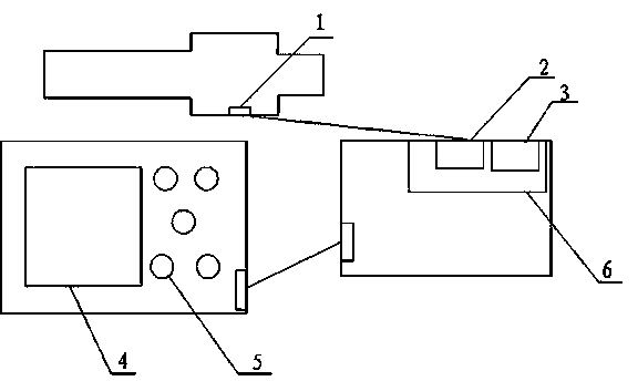
[0019] Such as figure 1 As shown, a wireless temperature measurement device includes: a wireless temperature measurement collection and transmission terminal 1 , a wireless signal receiving module 2 , a wireless signal processing module 3 , a display module 4 , a control module 5 , and a circuit board 6 .

[0020] The wireless temperature measurement acquisition transmitting terminal 1 and the wireless signal receiving module 2 adopt a 2.4GHz wireless signal transmission mode, and the wireless signal processing module 3 and the display module 4 are connected by a 16-core 2.54 data line.

[0021] The wireless temperature measurement collection and transmission terminal 1 is fixed in a strap-type silicone rubber jacket, and is pasted and fixed with 703 silica gel.

[0022] The wireless signal receiving module 2 and the wireless signal processing module 3 are welded on the circuit board 6 by using SMT welding technology. The modules are made of an aluminum alloy metal shell, and ...


PUM


Abstract

The invention discloses a wireless temperature measuring device. The wireless temperature measuring device comprises a wireless temperature measurement collecting and transmitting terminal, a wireless signal receiving and processing module and a display control module, wherein the wireless temperature measurement collecting and transmitting terminal and the wireless signal receiving and processing module adopt a 2.4GHz wireless signal transmitting mode, and the wireless signal receiving and processing module is connected with the display module by a 16-core 2.54 data line; the wireless temperature measurement collecting and transmitting terminal is fixedly arranged in a watchband type silicone rubber jacket; the wireless signal receiving and processing module is divided into a signal receiving part and a signal processing part, the display control module is divided into the two parts of a liquid crystal display screen and a control button, both the wireless signal receiving and processing module and the display control module are fixedly arranged on a circuit board in a welding mode, the modules adopt aluminum alloy casings, and the circuit board and the casings are fixed with each other by screws. The wireless temperature measuring device has the advantages of high safety, great reliability, small size, convenience in installation, convenience and flexibility in system wiring, visual display, simplicity and convenience in operation, convenience in site debugging and installation through a code matching function, no limitation on observation, real-time temperature measurement and intelligent signal sending, thereby ensuring the running reliability of the whole device.

Description

technical field [0001] The invention relates to a wireless temperature measuring device, which is applied in the field of electricity distribution. Background technique [0002] When the electrical equipment in the current transmission and distribution system is running, due to the high temperature, the insulation of the equipment is often damaged, causing failure or reducing the service life of the equipment. [0003] The current temperature measurement methods include temperature measurement patch, infrared temperature measurement, optical fiber temperature measurement, active wireless temperature measurement, etc., but each temperature measurement method has observation limitations, no intelligent alarm, difficult installation, and low reliability. The level of security is also low. [0004] The circuit breaker contacts in the high-voltage switchgear are in a closed state during operation, and the conventional method cannot detect the internal temperature or realize...

Claims


Application Information

Patent Timeline
Patent Type & Authority Applications(China)
IPC IPC(8): G01K1/02G01K1/024
Inventor 张宝勇于天浪梁前勇孟祥刚丁成才
Owner HEFEI HUIYUANCHENG ELECTRIC CO LTD
Learn More