
Battery pack temperature control system and control method thereof

A technology for temperature control systems and battery packs, applied to secondary batteries, circuits, electrical components, etc., can solve the problems of accelerated decline in battery pack life and performance, affecting the scope of use and promotion, and deflation, so as to improve power performance and Environmental adaptability, solve the problem that heat cannot be lost in time, and solve the effect of low charging and discharging efficiency

Active Publication Date: 2014-03-12
奇瑞新能源汽车股份有限公司
View PDF4 Cites 26 Cited by
  • Summary
  • Abstract
  • Description
  • Claims
  • Application Information

AI Technical Summary

Problems solved by technology

[0003] However, the internal chemical reaction of the high-voltage power lithium battery is not stable. Under high temperature or low temperature, improper charging and discharging of the high-voltage power lithium battery will generate a lot of heat. Leakage, outgassing, smoke, etc. will occur. In severe cases, the battery will burn violently and explode
At the same time, if the thermal management system of the battery pack cannot effectively ensure a uniform temperature field in the battery pack, it will cause the cells in the battery pack to work in different temperature ranges, resulting in an accelerated decline in battery pack life and performance.
In addition, the high-voltage power lithium battery cannot be charged or the charging efficiency is extremely low when the temperature is too low, which seriously affects the scope of its use and promotion.

Method used


Image

  • Battery pack temperature control system and control method thereof
  • Battery pack temperature control system and control method thereof
  • Battery pack temperature control system and control method thereof

Examples


Embodiment 1

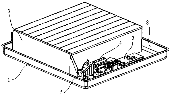
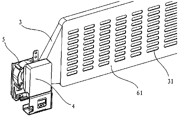
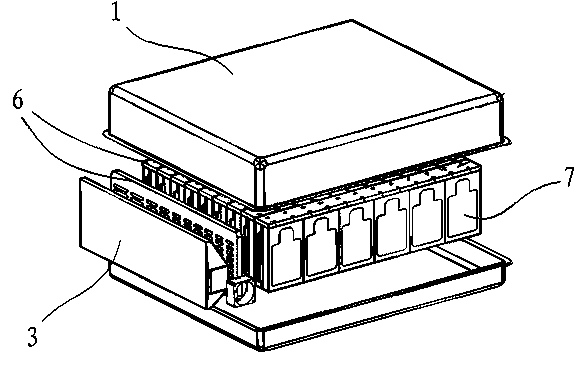
[0020] Such as figure 1 , 2 , 3 (the control unit is not shown in the figure), the battery pack temperature control system of this embodiment includes a battery pack case 1, a battery management unit 2 and a control unit, and the side of the battery pack case 1 is provided with The air duct 3, the air outlet 31 of the air duct 3 faces the direction of the battery inside the battery pack housing 1; the air inlet of the air duct 3 is provided with a PTC assembly 4 and a fan 5, and the PTC assembly 4, The fan 5 is powered by the charger or battery of the car, and the battery management unit 2, the PTC assembly 4, and the control switch of the fan 5 (which can be acted as a relay) are respectively connected with the control unit.

[0021] The side wall of the air duct 3 facing the battery is provided with a heat conduction plate 6, the heat conduction plate 6 is a double-layer plate structure, and one of the plates is a ventilation plate 61 with a needle-like fin structure, and s...


PUM


Abstract

The invention provides a battery pack temperature control system and a control method thereof. The battery pack temperature control system is simple in structure, low in cost and convenient to control. The battery pack temperature control system provided by the invention comprises a battery pack shell, a battery management unit and a control unit, wherein the battery pack shell is provided with an air flue, an air outlet of the air flue faces towards a battery inside the battery pack shell, a PTC (Positive Temperature Coefficient) assembly and a fan are arranged at an air inlet of the air flue, the PTC assembly and the fan are supplied with power by using a charger or a storage battery of an automobile, and the battery management unit, the PTC assembly and a control switch of the fan are respectively connected with the control unit. By adopting the battery pack temperature control system provided by the invention, the battery pack can be rapidly heated or cooled, the problem that the heat of the battery pack in a heavy-current discharge process can not be immediately dissipated is solved, the problem of low charge and discharge efficiency of the battery at a low temperature is also solved, and the power performance and the environment adaptive capacity of the battery pack are improved so that an electric vehicle can be used in a severe cold area in winter, and a wide application prospect is obtained.

Description

technical field [0001] The invention belongs to the development of a battery pack thermal management system, and more specifically relates to a battery pack temperature control system with heating and cooling functions and a control method thereof. Background technique [0002] The development of low-carbon economy requires new energy vehicles to achieve low consumption and low emissions, and requires the development of more advanced and more environmentally friendly technologies. The use of high-voltage power lithium batteries and the development of electric vehicles can enable new energy vehicles to achieve "zero emissions", thereby reducing energy consumption. [0003] However, the internal chemical reaction of the high-voltage power lithium battery is not stable. Under high temperature or low temperature, improper charging and discharging of the high-voltage power lithium battery will generate a lot of heat. There will be liquid leakage, outgassing, smoking and other p...

Claims


Application Information

Patent Timeline
IPC IPC(8): H01M10/635
CPCY02E60/10
Inventor 李勇周章根阎小军
Owner 奇瑞新能源汽车股份有限公司
Learn More