Hydraulic chuck clamp used for machining drum brake

A hydraulic chuck and brake drum technology, which is applied in chucks and other directions, can solve the problems of high technical level requirements for operators, unguaranteed machining accuracy, and high labor intensity of operators, so as to reduce the need for surface change and clamping The number of times and the number of handling, the improvement of production efficiency, and the effect of reducing deformation

Active Publication Date: 2014-03-19
HUBEI JINLIN MACHINERY MFG
View PDF8 Cites 7 Cited by
  • Summary
  • Abstract
  • Description
  • Claims
  • Application Information

AI Technical Summary

Problems solved by technology

[0002] Traditional hydraulic chucks are divided into 3-jaw chucks or 4-jaw chucks. The jaws are steel blocks with a trapezoidal structure, which can be used for external or internal clamping of the product. The traditional hydraulic chuck is used to clamp the brake drum of the car. During processing, the clamping direction cannot be automatically adjusted according to the internal and external shapes of the product. It is necessary to adjust the level of the workpiece by the operator to adjust the center point of the workpiece during processing. Multiple adjustments are required, which is time-consuming and labor-intensive. more demanding
And it is impossible to complete the rough and finish turning of the brake surface, reinforcing rib, dust-proof baffle seam, assembly seam and both ends of the brake drum at one time. During processing, the clamping plane must be replaced many times. It needs to be transported many times during the process, the labor intensity of the operators is high, the processing efficiency is low, and the processing accuracy cannot be guaranteed

Method used


Image

  • Hydraulic chuck clamp used for machining drum brake
  • Hydraulic chuck clamp used for machining drum brake
  • Hydraulic chuck clamp used for machining drum brake

Examples


Embodiment Construction

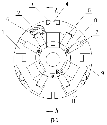
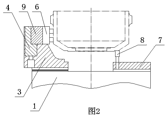
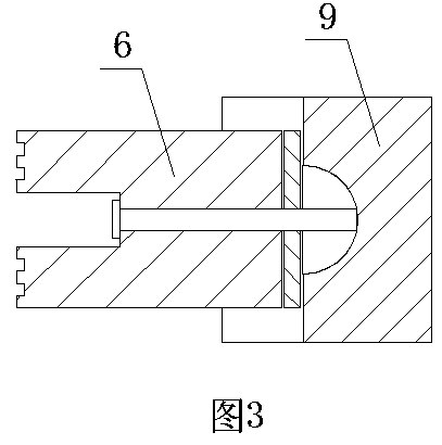
[0012] The hydraulic chuck fixture used for brake drum processing is composed of chuck body 1, base point block 7 and self-centering holder. Base point blocks 7 and self-centering decks are alternately installed in the grooves. The inner end of base point block 7 is equipped with base point screw rod 8, adjusts the height of workpiece by adjusting the height of base point screw rod 8, and base point block 7 can radially slide in the installation groove on chuck body 1 upper surface by manual. The self-centering deck is composed of a base 3, a rotating beam 9, a beam rotating shaft 4, two claw rotating shafts 2, two spacers 5 and two claws 6, and the rotating beam 9 connects with the base through the beam rotating shaft 4. The seat 3 is connected, the beam rotating shaft 4 can rotate in the base 3, the rotating beam 9 can swing left and right on the beam rotating shaft 4, and the two ends of the rotating beam 9 are respectively equipped with claws 6 and gaskets through the claw...


PUM


Abstract

The invention relates to a hydraulic chuck clamp used for machining a drum brake, and belongs to the technical field of clamps for machining the drum brake. The hydraulic chuck clamp is composed of a chunk body, base point blocks and automatic centering clamping bases, and the six base point blocks and the six automatic centering clamping bases are alternately installed on the chunk body. A base point screw rod is installed on every base point block; every automatic centering clamping base is composed of a substrate, a rotating beam, a beam rotating shaft, two clamping jaw rotating shafts, two gaskets and two clamping jaws, wherein the rotating beam is connected with the substrate through the bean rotating shaft, and the clamping jaws and the gaskets are installed at the two ends of the rotating beam. The hydraulic chuck clamp can automatically capture the center point of a workpiece, ensure the coaxiality and levelness of workpiece clamping, finish rough and fine turning on a braking face, reinforcing ribs, a spigot of a dust-proof baffle, an assembly spigot and the two end faces of the drum brake in a one-off mode, improve machining efficiency and save time and labor, and the production benefits are improved by 2.5 times. The problems that when the drum brake is machined in a traditional mode, people need to replace clamping planes repeatedly, time and labor are wasted, and machining accuracy can not be ensured are solved.

Description

technical field [0001] The invention relates to a hydraulic chuck fixture used for brake drum processing, which belongs to the technical field of brake drum processing fixtures. Background technique [0002] Traditional hydraulic chucks are divided into 3-jaw chucks or 4-jaw chucks. The jaws are steel blocks with a trapezoidal structure, which can be used for external or internal clamping of the product. The traditional hydraulic chuck is used to clamp the brake drum of the car. During processing, the clamping direction cannot be automatically adjusted according to the internal and external shapes of the product. It is necessary to adjust the level of the workpiece by the operator to adjust the center point of the workpiece during processing. Multiple adjustments are required, which is time-consuming and labor-intensive. Higher requirements. And it is impossible to complete the rough and finish turning of the brake surface, reinforcing rib, dust-proof baffle seam, assembly ...

Claims


Application Information

Patent Timeline
Patent Type & Authority Applications(China)
IPC IPC(8): B23B31/30
CPCB23B31/30
Inventor 张志军
Owner HUBEI JINLIN MACHINERY MFG
Why Eureka
Try Eureka