Vehicle gear recognition method and device

A technology of identification device and identification method, which is applied in the direction of vehicle components, transmission control, transportation and packaging, etc., can solve the problems of increased difficulty, error-prone identification, failure of gear acquisition function, etc., and achieves easy engineering implementation, easy layout, The effect of simple structure

Active Publication Date: 2014-03-19
ATSUMITEC AUTO PARTS (FOSHAN) CO LTD
View PDF4 Cites 11 Cited by
  • Summary
  • Abstract
  • Description
  • Claims
  • Application Information

AI Technical Summary

Problems solved by technology

[0003] In order to accurately identify the driver's gear position operation, in the existing gear position recognition application technology, there are usually the following methods: one is a mechanical touch switch signal detection device, through various contact or non-contact The switch sensor of the switch acquires the switch signal of each gear to judge the state of the gear at the end of the driver's shifting action. The disadvantage of this scheme is that when the gear increases, the number of gear switch sensors will be increased accordingly. It is more difficult to actually arrange th

Method used


Image

  • Vehicle gear recognition method and device
  • Vehicle gear recognition method and device
  • Vehicle gear recognition method and device

Examples


no. 1 example

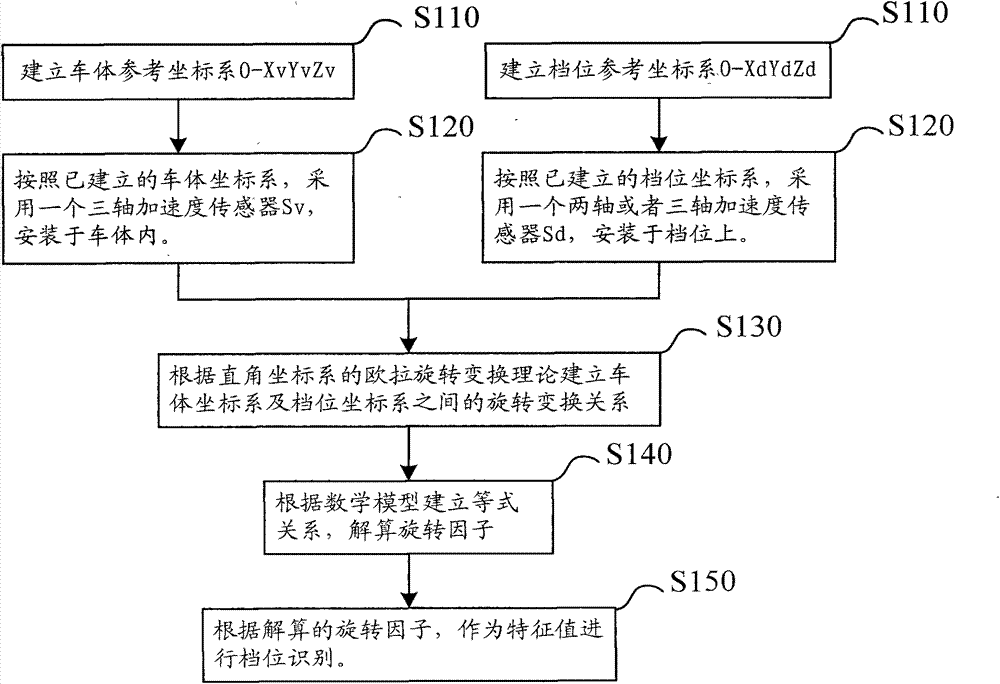
[0040] figure 1 It is a flow chart of the method for automatically identifying the gear position of a vehicle. The following is based on figure 1 Each step of this embodiment will be described in detail.

[0041] Step S110: Establishing the vehicle body reference coordinate system O-XvYvZv and the gear position reference coordinate system O-XdYdZd;

[0042] Step S120: According to the established coordinate system of the vehicle body, adopt a three-axis acceleration sensor Sv and install it in the vehicle body; according to the established gear position coordinate system, adopt a two-axis or three-axis acceleration sensor Sd and install it on the gear position ;

[0043] The acceleration sensor installed in the gear position preferably adopts a three-axis acceleration sensor.

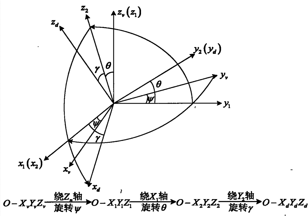
[0044] Step S130: Establish the rotation transformation relationship between the car body coordinate system and the gear coordinate system according to the Euler rotation transformation theory of the...

no. 2 example

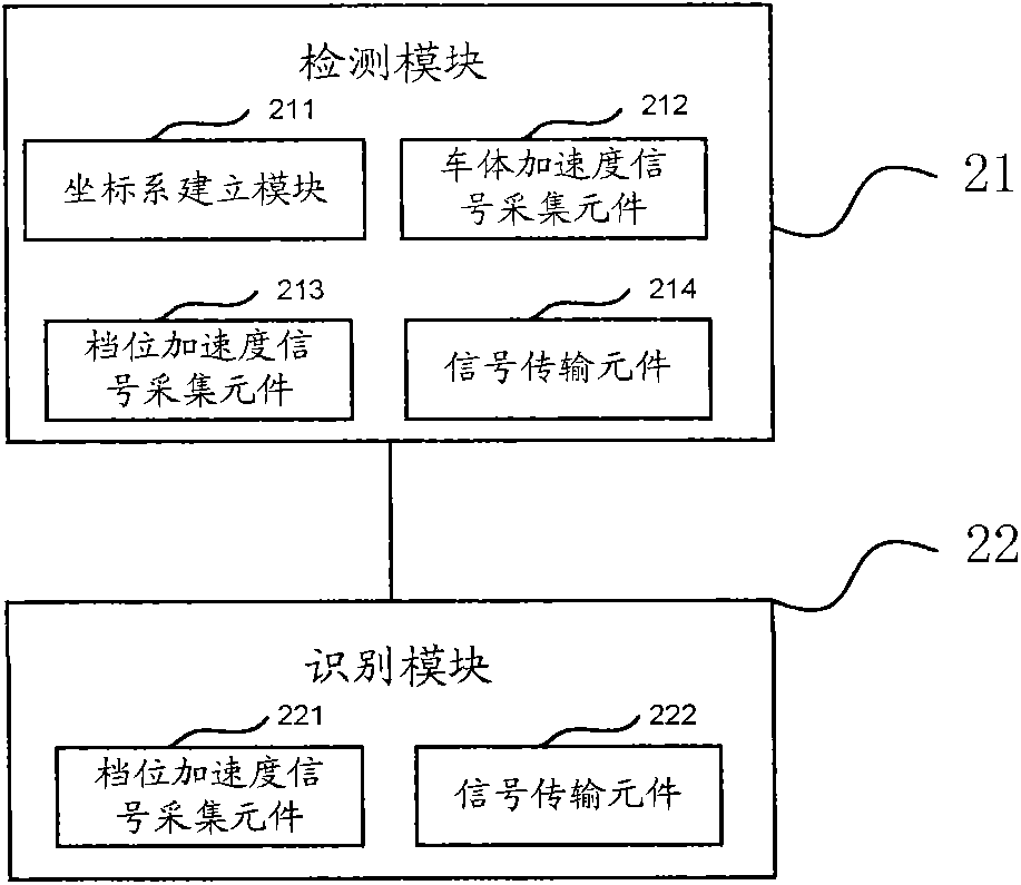
[0075] image 3 It is the module diagram of the gear recognition device, refer to the following figure 2 This example will be described. In the present invention, it mainly includes an inspection module 21 and an identification module 22 .


PUM


Abstract

The invention discloses a vehicle gear recognition method and device. The method includes the steps of building a vehicle body reference coordinate system and a gear reference coordinate system, collecting a vehicle body acceleration signal according to a built vehicle body coordinate system, and collecting a gear acceleration signal according to a built gear coordinate system. According to an Euler rotation transformation theory of a right-angle coordinate system, a rotation transformation relationship between the vehicle body coordinate system and the gear coordinate system is built, an equation relationship between a vehicle body acceleration vector and a gear acceleration vector is built according to the rotation transformation relationship between the vehicle body coordinate system and the gear coordinate system, a rotation factor between the gear reference coordinate system and the vehicle body reference coordinate system is solved according to the built equation relationship, and the rotation factor serves as a feature value for gear recognition. The method has the advantages of being simple in structure, easy to arrange and easy to achieve in a project. The state of a gear can be recognized when a vehicle runs under actual road conditions and a gear shifting motion is finished.

Description

technical field [0001] The invention relates to the field of vehicle gear recognition, in particular to a vehicle gear recognition method and device. Background technique [0002] In the assessment of the driver by the traffic management department, the driver is required to perform the corresponding operation according to the prescribed gear, otherwise it will be regarded as unqualified or deducted points. [0003] In order to accurately identify the driver's gear position operation, in the existing gear position recognition application technology, there are usually the following methods: one is a mechanical touch switch signal detection device, through various contact or non-contact The switch sensor of the switch acquires the switch signal of each gear to judge the state of the gear at the end of the driver's shifting action. The disadvantage of this scheme is that when the gear increases, the number of gear switch sensors will be increased accordingly. It is more diffic...

Claims


Application Information

Patent Timeline
IPC IPC(8): B60K35/00B60R16/02F16H61/12
Inventor 胡秋立
Owner ATSUMITEC AUTO PARTS (FOSHAN) CO LTD
Why Eureka
Try Eureka