Electric cable winding machine

A technology of power cable and wire take-up machine, which is applied in the direction of conveying filamentous materials, thin material handling, transportation and packaging, etc. It can solve the problems of potential safety hazards, uneven winding, low operating efficiency, etc., and achieve convenient maintenance Operation, high operation efficiency and good effect

Inactive Publication Date: 2014-03-19
国网山东省电力公司郯城县供电公司 +1
View PDF5 Cites 13 Cited by
  • Summary
  • Abstract
  • Description
  • Claims
  • Application Information

AI Technical Summary

Problems solved by technology

[0002] Cable take-up reels are often used in electric power repair operations to wind up the cables. The existing operations are manually operate

Method used


Image

  • Electric cable winding machine
  • Electric cable winding machine
  • Electric cable winding machine

Examples


Embodiment Construction

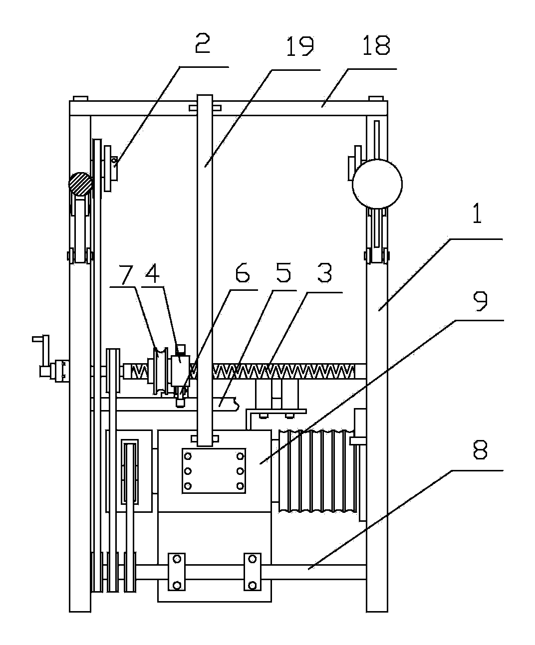
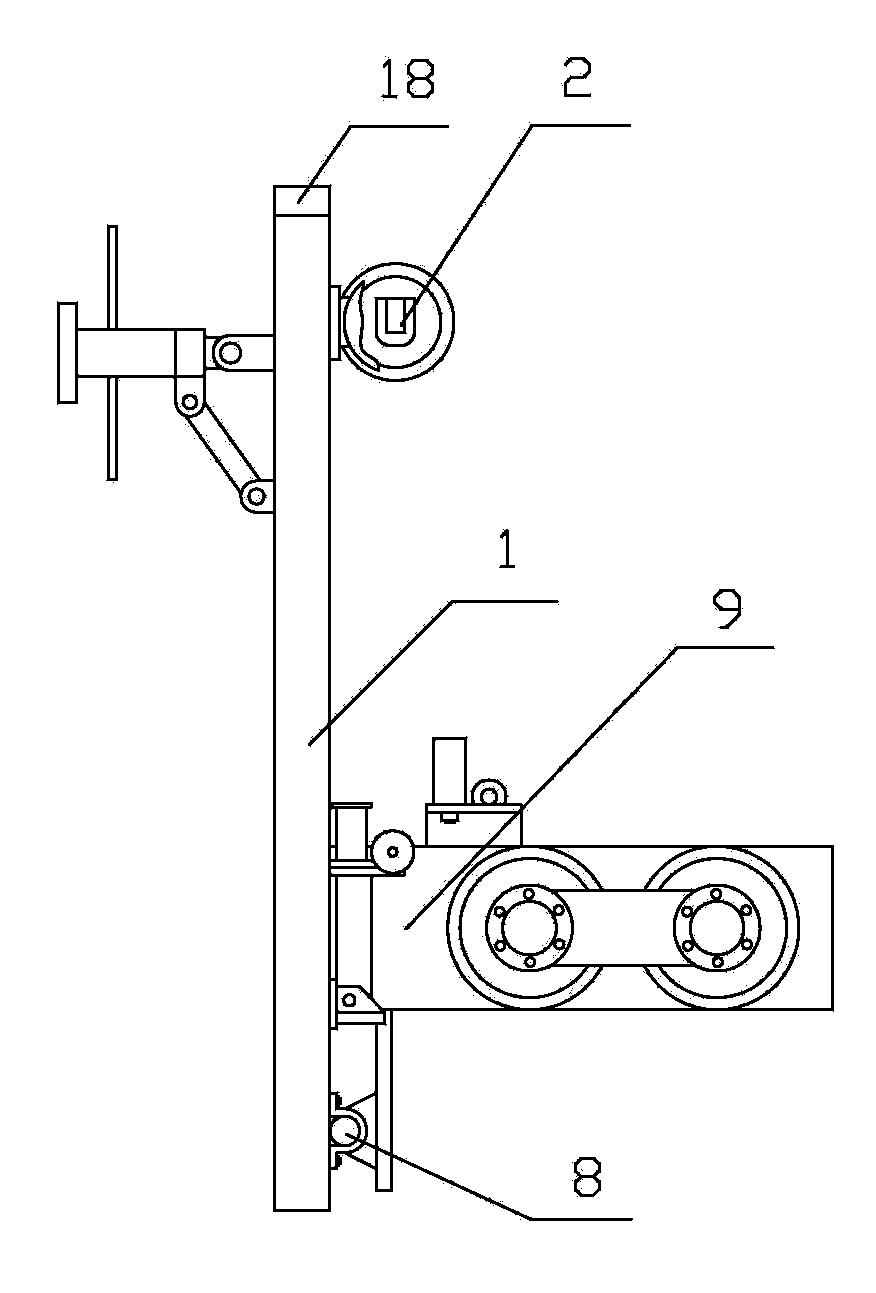
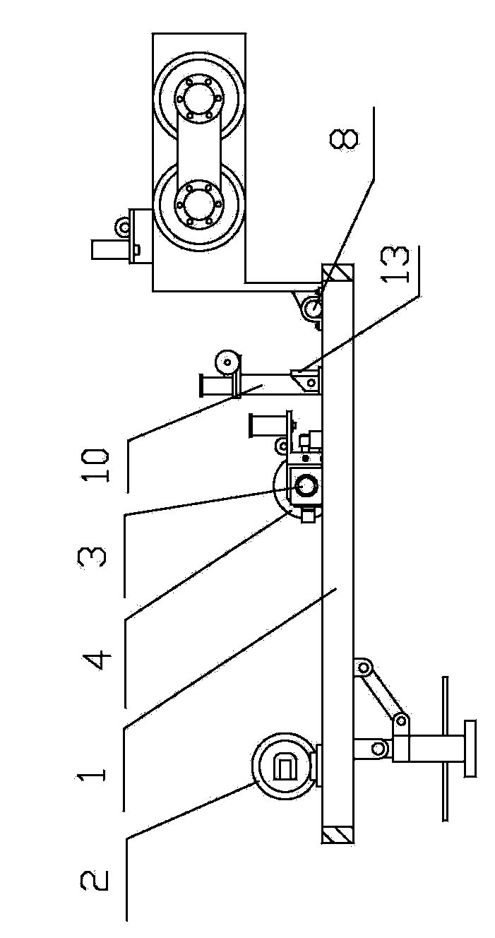
[0015] Such as figure 1 As shown, the power cable take-up machine of the present invention includes a bracket 1 of a rectangular frame structure, a wire roller shaft seat 2 mounted on the rear end of the bracket 1 through a bearing, and a power input shaft 8 is provided at the front end of the bracket 1, The power input shaft 8 is hinged on the housing of the power machine 9 through a shaft seat, the rear end of the bracket 1 is fixedly connected with a beam 18, one end of the pull rod 19 is hinged on the beam 18, and the other end of the pull rod 19 is hinged on the housing of the power machine 9 On, above the input shaft 8. The pins at both ends of the pull rod 19 are pulled out, and the pull rod 19 is taken off, then the support 1 can be as follows: figure 2 Shown lay down and in working condition. When packing up, the rear end of support 1 is lifted to make it in an upright state, and then the two ends of pull rod 19 are fixed with pins respectively, then support 1 can ...


PUM


Abstract

The invention relates to electrical equipment, in particular to an electric cable winding machine. The electric cable winding machine comprises a bracket adopting a rectangular frame structure and a cable roll shaft seat mounted at the rear end of the bracket through a bearing, wherein a power input shaft is arranged at the front end of the bracket; a bidirectional screw rod is mounted in the middle of the bracket through a bearing; the power input shaft is in transmission connection with the cable roll shaft seat, the bidirectional screw rod and a power machine through a chain and chain wheel pair respectively; a flat cable tackle is nested on the bidirectional screw rod; a slide track is fixedly mounted on the bracket and is parallel to the bidirectional screw rod; and the flat cable tackle is fixedly connected with a supporting rod mounted in the slide track, and a flat cable pulley is mounted on the flat cable tackle through a bearing. The electric cable winding machine adopts the power machine such as a tractor and the like as drive mechanisms to replace manpower operation, the operation efficiency is high, a cable can be uniformly wound around a take-up reel by means of a cabling mechanism, the cable winding quality is high, and the cable winding effect is good; and the cable wound around the take-up reel can be conveniently detached, and the maintenance operation is facilitated.

Description

technical field [0001] The invention relates to a power device, in particular to a power cable take-up machine. Background technique [0002] Cable take-up reels are often used in electric power repair operations to wind up the cables. The existing operations are manually operated, which not only has high labor intensity and low operation efficiency, but also has defects such as uneven winding and potential safety hazards. Contents of the invention [0003] To solve the above problems, the present invention provides a power cable take-up machine with simple structure, high winding quality and good effect. [0004] The technical scheme that the present invention adopts for solving technical problems is: [0005] The power cable take-up machine of the present invention includes a bracket with a rectangular frame structure, a wire roller shaft seat mounted on the rear end of the bracket through a bearing, a power input shaft is provided at the front end of the bracket, and a...

Claims


Application Information

Patent Timeline
IPC IPC(8): B65H54/10B65H54/28B65H57/14B65H75/14B65H75/22B65H75/20
Inventor 密士锋娄向华刘洪波刘畅
Owner 国网山东省电力公司郯城县供电公司
Why Eureka
Try Eureka