
Automatic speed adjustment type cable robot

A self-speed-adjusting, robotic technology, applied in bridge parts, bridges, buildings, etc., can solve the problems of difficulty in automatic adjustment of the speed when energy is returned, high consumption of robots, and difficulty in returning to the ground automatically, so as to prevent cable piercing accidents and save energy Energy, damage avoidance effects

Active Publication Date: 2014-03-19
平湖市中劢磁业股份有限公司
View PDF7 Cites 6 Cited by
  • Summary
  • Abstract
  • Description
  • Claims
  • Application Information

AI Technical Summary

Problems solved by technology

[0005] Aiming at the problems that the existing cable robot is difficult to automatically return to the ground when the power is unexpectedly cut off, the robot consumes a lot of energy when returning to the ground normally, and the speed is difficult to automatically adjust when returning, the present invention provides a self-adjusting cable robot

Method used


Image

  • Automatic speed adjustment type cable robot
  • Automatic speed adjustment type cable robot
  • Automatic speed adjustment type cable robot

Examples


Embodiment 1

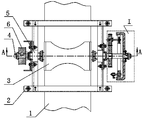
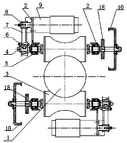
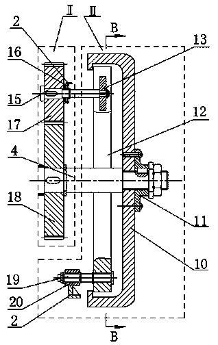
[0030] Such as figure 1 , figure 2 , image 3 , Figure 4 As shown, the self-adjusting cable robot includes a frame 2, a roller 3, a main shaft 4, a rolling bearing A5, a synchronous pulley A6, a synchronous belt 7, a synchronous pulley B8, and a synchronous motor 9. The frame 2 is provided with a rolling bearing A5, Synchronous motor 9, the main shaft 4 is assembled in the rolling bearing A5, one end of the main shaft 4 is connected with the synchronous pulley A6, the roller 3 is assembled on the main shaft 4, the arc surface of the roller 3 is pressed on the surface of the cable 1, and the synchronous pulley B8 is assembled on the synchronous motor 9 On the main shaft, the synchronous pulley A6 and the synchronous pulley B8 are both meshed with the synchronous belt 7; the self-adjusting speed cable robot also includes the return mechanism I, and the return mechanism I is braked by the speed increase mechanism II and the inner expansion block. Institution Ⅲ constitutes. ...

Embodiment 2

[0035] Such as figure 1 , figure 2 , image 3 , Figure 4 As shown, the self-adjusting cable robot includes a frame 2, a roller 3, a main shaft 4, a rolling bearing A5, a synchronous pulley A6, a synchronous belt 7, a synchronous pulley B8, and a synchronous motor 9. The frame 2 is provided with a rolling bearing A5, Synchronous motor 9, the main shaft 4 is assembled in the rolling bearing A5, one end of the main shaft 4 is connected with the synchronous pulley A6, the roller 3 is assembled on the main shaft 4, the arc surface of the roller 3 is pressed on the surface of the cable 1, and the synchronous pulley B8 is assembled on the synchronous motor 9 On the main shaft, the synchronous pulley A6 and the synchronous pulley B8 are both meshed with the synchronous belt 7; the self-adjusting speed cable robot also includes the return mechanism I, and the return mechanism I is braked by the speed increase mechanism II and the inner expansion block. Institution Ⅲ constitutes. ...


PUM


Abstract

The invention discloses an automatic speed adjustment type cable robot and belongs to the field of special robots. The cable robot comprises a frame, a roller wheel, a main shaft, a rolling bearing A, a synchronous belt wheel A, a synchronous belt, a synchronous belt wheel B, a synchronous motor and a return stroke mechanism, wherein the return stroke mechanism comprises a speed increment mechanism and an internal expansion block type brake mechanism; the speed increment mechanism comprises a transmission shaft, a rolling bearing B, a gear B and a gear A; the internal expansion block type brake mechanism comprises a brake wheel, a flange plate, a brake shoe, a cam, a tension spring, a rotary shaft and a shaft sleeve. The cable robot solves the problems that an existing cable robot hardly and automatically returns to the ground in case of unexpected power outage and a large amount of energy is consumed and the speed is not easy to adjust automatically when the robot normally returns to the ground, and has the advantages of reasonable design and simplicity for manufacturing.

Description

technical field [0001] The invention belongs to the field of special robots, and more specifically relates to a self-adjusting speed cable robot for cable detection and maintenance. Background technique [0002] As a new form of modern bridge, cable-stayed bridge has been widely used in the world. As one of the main stress-bearing components of cable-stayed bridges, the cable is exposed to the air for a long time, and the polyethylene sheath on the surface of the cable will be hardened and cracked to varying degrees after being exposed to wind, rain and sun. Serious problems such as rust spots and broken wires are caused by the bundles; at the same time, due to random wind and rain vibrations, the steel wires in the cables produce micro-friction, which in turn causes serious broken wires, burying serious hidden dangers for the cable-stayed bridge. Since the cable-stayed bridge is a new type of bridge that has only emerged in recent decades, the cable maintenance measures ma...

Claims


Application Information

Patent Timeline
IPC IPC(8): E01D19/10
Inventor 包贤强冷护基
Owner 平湖市中劢磁业股份有限公司
Learn More