
A corrugated welded reinforced steel plate-concrete composite shear wall

A technology of combining shear walls and corrugated steel plates, applied to building reinforcements, walls, structural elements, etc., can solve the problems of easy loosening of metal cover plates, potential safety hazards, uneven ground, etc., and achieve improved out-of-plane stiffness, Improve ductility, good restraint effect

Active Publication Date: 2018-04-10
广州市设计院集团有限公司
View PDF7 Cites 0 Cited by
  • Summary
  • Abstract
  • Description
  • Claims
  • Application Information

AI Technical Summary

Problems solved by technology

[0008] The purpose of the present invention is to provide a wave welded reinforced steel plate-concrete composite shear wall in order to overcome the defects of the prior art that the plane deformation joints are easy to cause uneven ground, the metal cover plate is easy to loosen, and there are potential safety hazards.

Method used


Image

  • A corrugated welded reinforced steel plate-concrete composite shear wall
  • A corrugated welded reinforced steel plate-concrete composite shear wall
  • A corrugated welded reinforced steel plate-concrete composite shear wall

Examples


specific Embodiment 1

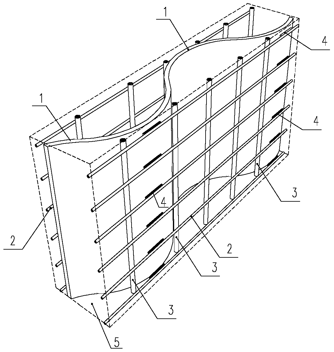
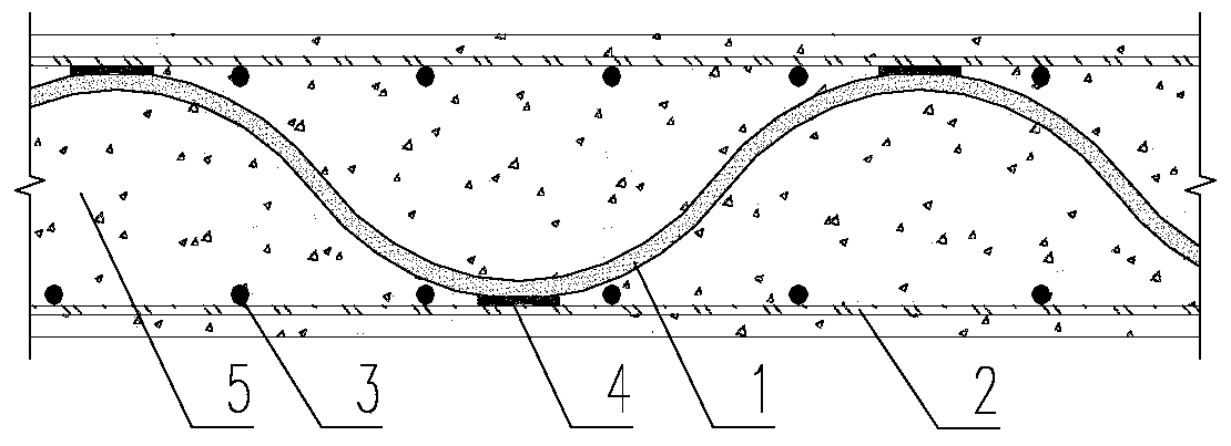
[0031] refer to figure 1 and figure 2 , this embodiment includes a concrete wall 5 and a steel bar structure built in the concrete wall 5, characterized in that: the steel bar structure is a wave-welded reinforced structure, including a corrugated steel plate 1, a horizontally distributed bar structure 2 and a vertically distributed bar structure 3, The horizontal distribution bar structure 2 is composed of several pairs of horizontally arranged steel bars, and the vertical distribution bar structure 3 is composed of several pairs of vertically arranged steel bars; the horizontal distribution bar structure 2 and the vertical distribution bar structure 3 are connected to form the concrete wall 5 The frame-shaped support structure, the corrugated steel plate 1 is located in the frame-shaped support structure, and the corrugated steel plate 1 is welded and connected with the horizontally distributed ribs or vertically distributed ribs of the frame-shaped support structure at the...

specific Embodiment 2

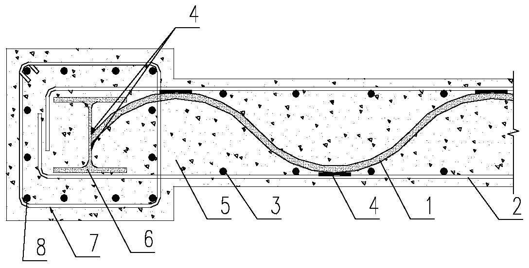
[0036] refer to image 3 , the characteristics of this embodiment 2 are: the steel plate-concrete composite shear wall includes a rectangular part and a thickened part, and the concrete wall 5 and the steel structure built in the concrete wall 5 include a rectangular part and a rectangular part. The thickened part extending from one end of the part has an "I"-shaped steel reinforcement 6 built in the thickened part, and several end longitudinal ribs 8 and several stirrups 7 are arranged in the thickened part. The corrugated steel plate 1 extends to The thickened part is fixedly connected with the "I"-shaped steel reinforcement 6, that is, a welded connection structure 4 is formed through welding connection; it consists of several end longitudinal ribs 8, several stirrup bars 7, "I"-shaped steel reinforcement 6 and corrugated steel plates 1 Form the corrugated welding reinforcement structure of the thickened part. This embodiment can effectively improve the bending resistance ...

specific Embodiment 3

[0037] refer to Figure 4 , the characteristics of this embodiment 3 are: the steel plate-concrete composite shear wall is rectangular, the concrete wall 5 and the reinforcement structure built in the concrete wall 5 are rectangular, and the end of the shear wall is provided with The semi-corrugated steel plate 9 is welded with the corrugated steel plate 1 to form a drop-shaped steel pipe column. Concrete 5 is poured inside the steel pipe column to form a steel pipe concrete column as a concealed column at the end of the shear wall.

[0038] This embodiment can provide better restraint to the internal concrete, and the transition to the corrugated steel plate 1 is also smoother. Therefore, it can be used in buildings with higher ductility requirements.

[0039] During construction, one room of corrugated steel plates between different floors can be connected by groove butt welding. The vertically distributed tendon structure 3 is inserted and bound from top to bottom. The v...


PUM


Abstract

The invention relates to a wave-welded reinforced steel plate-concrete combined shear wall, which includes a concrete wall and a steel bar structure built in the concrete wall, and is characterized in that: the steel bar structure is a wave-welded reinforced structure, including a wave-shaped steel plate and horizontally distributed bars Structure and vertical distribution reinforcement structure, the horizontal distribution reinforcement structure is composed of several pairs of steel bars arranged horizontally, the vertical distribution reinforcement structure is composed of several pairs of vertical distribution reinforcement bars; the horizontal distribution reinforcement structure and the vertical distribution reinforcement structure are connected to form concrete The frame-shaped supporting structure of the wall, the corrugated steel plate is located in the frame-shaped supporting structure, and the corrugated steel plate is welded and connected with the horizontal distribution ribs or vertical distribution ribs of the frame-shaped support structure at the peaks and troughs to form a wave-welded reinforced hybrid shear. force support structure. In the invention, corrugated steel plates are placed in the reinforced concrete shear wall, and the corrugated steel plates are welded and connected to the horizontal distribution bars or vertical distribution bars of the frame support structure at the peaks and troughs. The utility model has good integrity between the steel plate and the concrete, and can provide a beneficial effect of better restraint on the concrete.

Description

technical field [0001] The invention relates to a corrugated welded reinforced steel plate-concrete composite shear wall, which can be used in large comprehensive high-rise buildings. It belongs to the field of architectural structure design. Background technique [0002] With the development of the economy, high-rise and super high-rise buildings emerge in an endless stream. As the height of the building increases, as the main anti-lateral force component in the building—the shear wall, if it adopts the traditional reinforced concrete form, not only the thickness will be too thick to affect the use, but also The economy is poor and the security is low. Therefore, the steel-concrete composite shear wall came into being. [0003] In the prior art, steel-concrete composite shear walls mainly include steel-concrete composite shear walls, steel plate-concrete composite shear walls, steel pipe-concrete composite shear walls, steel support-concrete composite shear walls, etc. A...

Claims


Application Information

Patent Timeline
Patent Type & Authority Patents(China)
IPC IPC(8): E04B2/56E04C5/03
Inventor 王一功米强韩建强
Owner 广州市设计院集团有限公司
Learn More