Distributor suitable for shell and tube heat exchangers

A shell-and-tube heat exchanger and distributor technology, which is applied in the direction of heat exchanger shell, heat exchange equipment, lighting and heating equipment, etc., can solve the problems of inability to achieve uniform distribution of medium and simple structure, and achieves simple structure and improved performance. Flow rate, to achieve the effect of even distribution

Active Publication Date: 2014-03-19
XINCHANG JINGXIN PRECISION MACHINERY PARTS CO LTD
View PDF5 Cites 1 Cited by
  • Summary
  • Abstract
  • Description
  • Claims
  • Application Information

AI Technical Summary

Problems solved by technology

[0002] The distributor in the shell-and-tube heat exchanger in the prior art, such as a single-tube shell-and-tube heat exchanger with a distributor disclosed in the utility model patent with the authorized announcement number CN2711674Y, involves the distribution The device, whose structure is too simple, cannot achieve uniform distribution of the medium, especially for the tube-side medium with complex vapor-liquid two-phase

Method used


Image

  • Distributor suitable for shell and tube heat exchangers
  • Distributor suitable for shell and tube heat exchangers

Examples


Embodiment 1

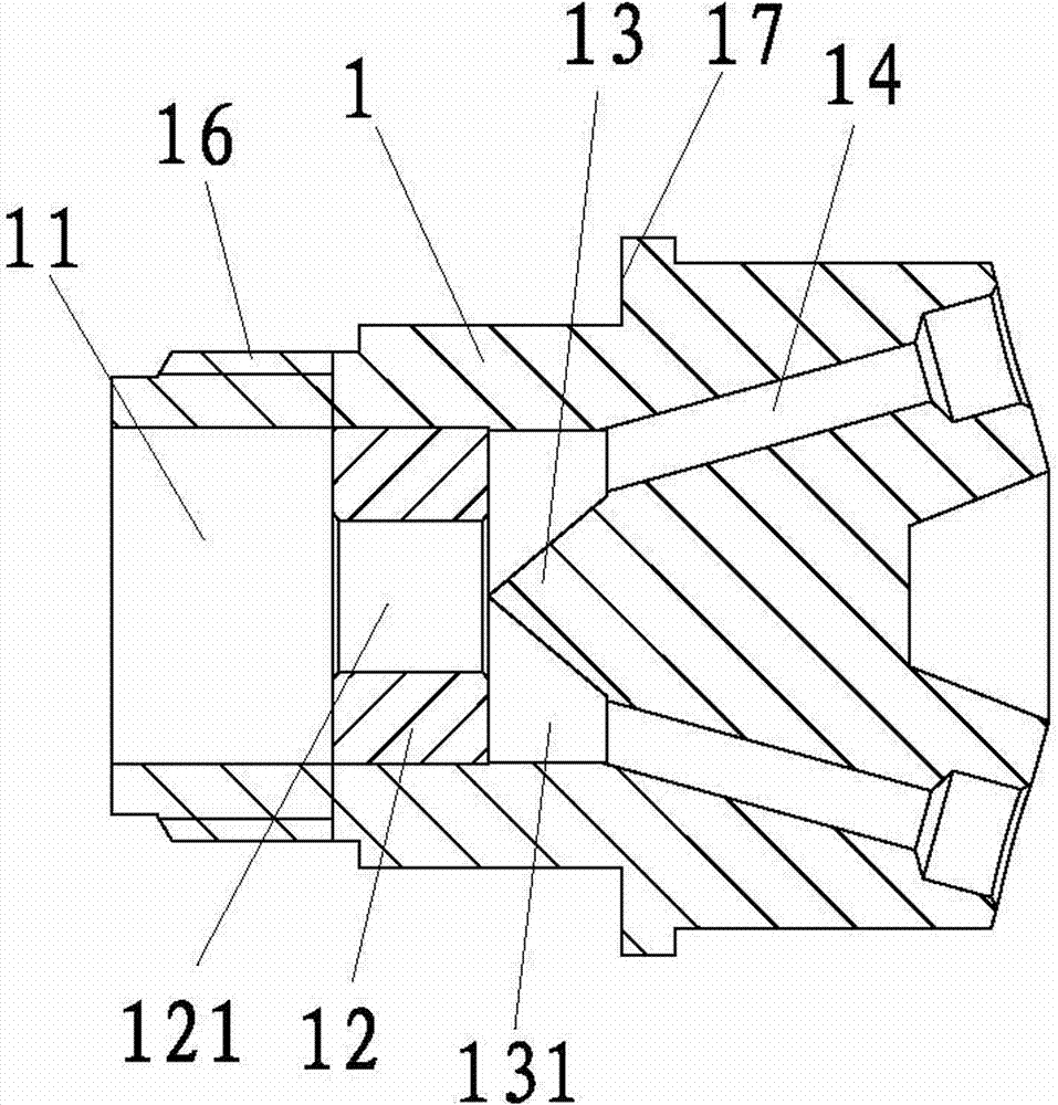
[0015] Embodiment 1: A distributor suitable for shell and tube heat exchangers, such as figure 1 As shown, it includes the body 1 and the medium channel 11, the throttling speed-up plate 12, the breaking body 13 and the distribution channel 14 which are sequentially arranged on the body 1 along the medium flow direction; the mixing body 13 and the throttle speed-up plate 12 form a mixed Cavity 131; throttle speed-up plate 12 middle part has speed-up hole 121; Scattered body 13 is the conical body whose axis coincides with the speed-up hole 121 axis, and the present embodiment is a cone; A plane close to the surface of the cone; the distribution channel 14 communicates with the mixing chamber 131 and is evenly distributed around the dispersing body 13; the distance between the axis of the distribution channel 14 and the axis of the cone gradually increases along the medium advancing direction; the speed-up hole 121 The diameter of the end close to the breaking body 13 is smalle...

Embodiment 2

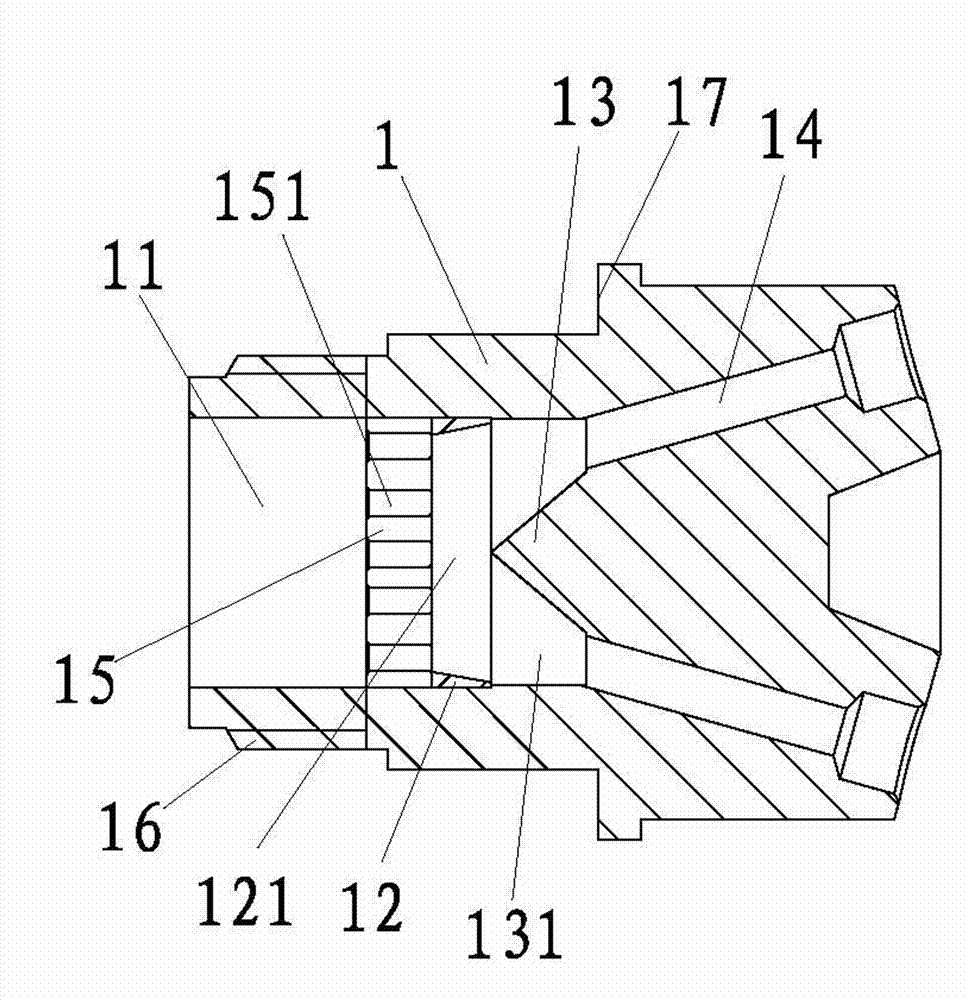
[0017] Embodiment 2: as figure 2 As shown, the difference from Embodiment 1 is that, along the forward direction of the medium, the rear end of the throttling speed-up plate 12 in the body 1 is provided with a flow equalizer 15 having a plurality of through holes 151 communicating with the speed-up holes 121; The diameter of the speed-up hole 121 increases gradually along the medium advancing direction; the entrance of the through hole 151 has a diameter-reducing section, that is, the diameter of this section gradually decreases along the medium advancing direction.


PUM


Abstract

The invention relates to shell and tube heat exchangers, in particular to a distributor suitable for the shell and tube heat exchangers. According to the technical scheme, the distributor suitable for the shell and tube heat exchangers comprises a body, a medium channel, a throttling and accelerating plate, a scattering body and distributing channels, wherein the medium channel, the throttling and accelerating plate, the scattering body and the distributing channels are arranged on the body in the medium flowing direction in sequence. A mixing chamber is formed between the scattering body and the throttling and accelerating plate, an accelerating hole is formed in the middle of the throttling and accelerating plate, the scattering body is a cone-shaped body with the axis coincident with the axis of the accelerating hole, the cone tip of the cone-shaped body is located on the plane where one surface, close to the cone-shaped body, of the throttling and accelerating plate is located, the distributing channels are communicated with the mixing chamber and are evenly distributed around the scattering body, and the distance between the axes of the distribution channels and the axis of the cone-shaped body is gradually enlarged in the proceeding direction of the medium. The distributor suitable for the shell and tube heat exchangers can achieve even distribution on the medium effectively.

Description

technical field [0001] The invention relates to a shell-and-tube heat exchanger, in particular to a distributor suitable for the shell-and-tube heat exchanger. Background technique [0002] The distributor in the shell-and-tube heat exchanger in the prior art, such as a single-tube shell-and-tube heat exchanger with a distributor disclosed in the utility model patent with the authorized announcement number CN2711674Y, involves the distribution The device, whose structure is too simple, cannot realize the uniform distribution of the medium, especially for the tube-side medium with complex vapor-liquid two-phase. Contents of the invention [0003] The purpose of the present invention is to provide a distributor suitable for shell and tube heat exchangers, which can effectively realize the uniform distribution of the medium. [0004] The above technical purpose of the present invention is achieved through the following technical solutions: a distributor suitable for shell an...

Claims


Application Information

Patent Timeline
IPC IPC(8): F28F9/22
Inventor 赵茂江
Owner XINCHANG JINGXIN PRECISION MACHINERY PARTS CO LTD
Why Eureka
Try Eureka