High-voltage ignition relay and operating method thereof

A high-voltage ignition and relay technology, applied in the direction of instruments, weapon accessories, electrical components, etc., can solve the problems that do not meet the requirements of high-voltage pyrotechnic explosion ignition, do not meet the safety requirements of weapon systems, and have no insurance agencies, etc., to achieve a good weapon system The effect of matching adaptive performance, improving anti-interference ability, and improving safety

Active Publication Date: 2014-03-19
G & A TECH
View PDF4 Cites 12 Cited by
  • Summary
  • Abstract
  • Description
  • Claims
  • Application Information

AI Technical Summary

Problems solved by technology

At present, the traditional pyrotechnic ignition circuit of the weapon system uses low voltage (DC 27V) and small current (10A) to ignite. Since the traditional pyrotechnic ignition circuit uses an electromechanical isolation safety device to isolate the insensitive ignition element, it will be even worse in the future. There are unsafe factors in both the electromagnetic environment and the mechanical environment
However, the existing high-pressure ignition systems and schemes are mainly aimed at oil, combustible gases, solids and powders for combustion ignition control, which do not meet the requirements for explosion ignition of high-pressure pyrotechnics in weapon systems, and do not have reliable insurance mechanisms, which do not meet the requirements of weapon systems. Overall System Security Requirements

Method used


Image

  • High-voltage ignition relay and operating method thereof
  • High-voltage ignition relay and operating method thereof
  • High-voltage ignition relay and operating method thereof

Examples


Embodiment Construction

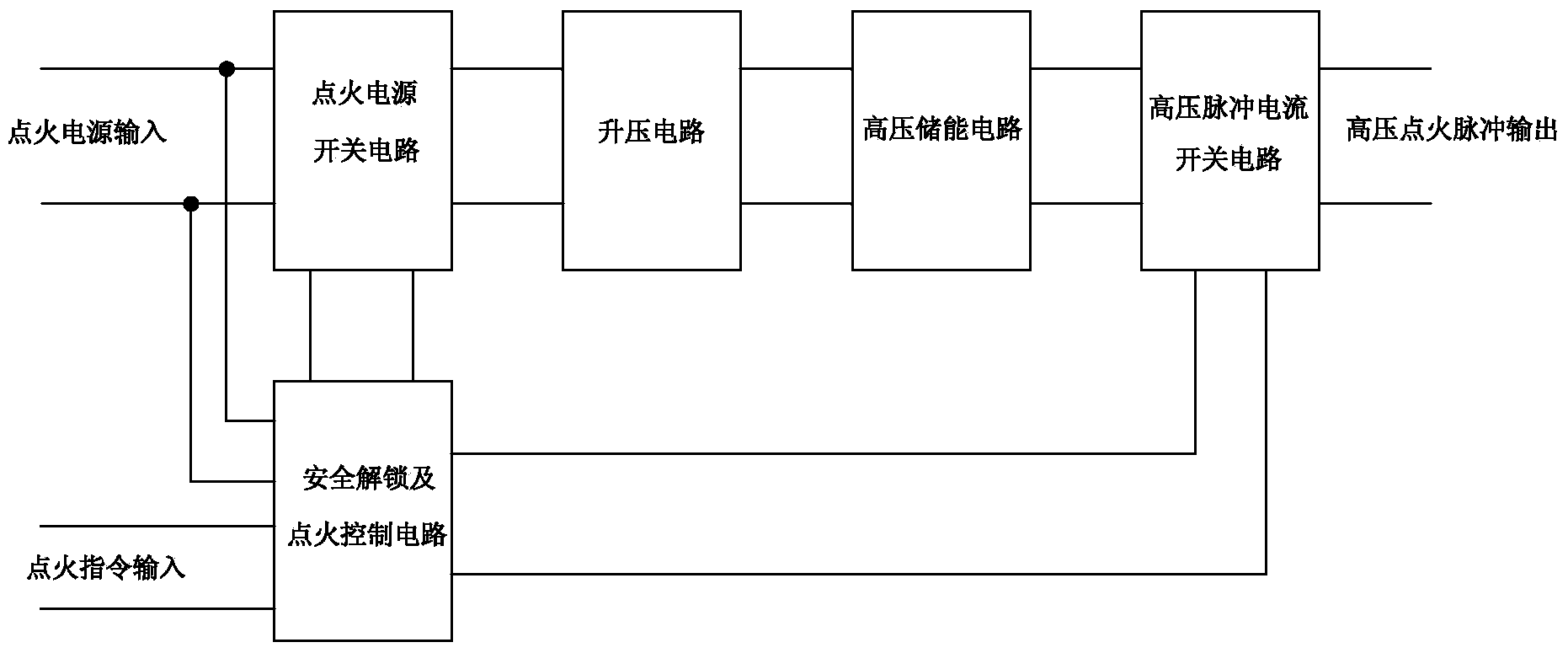
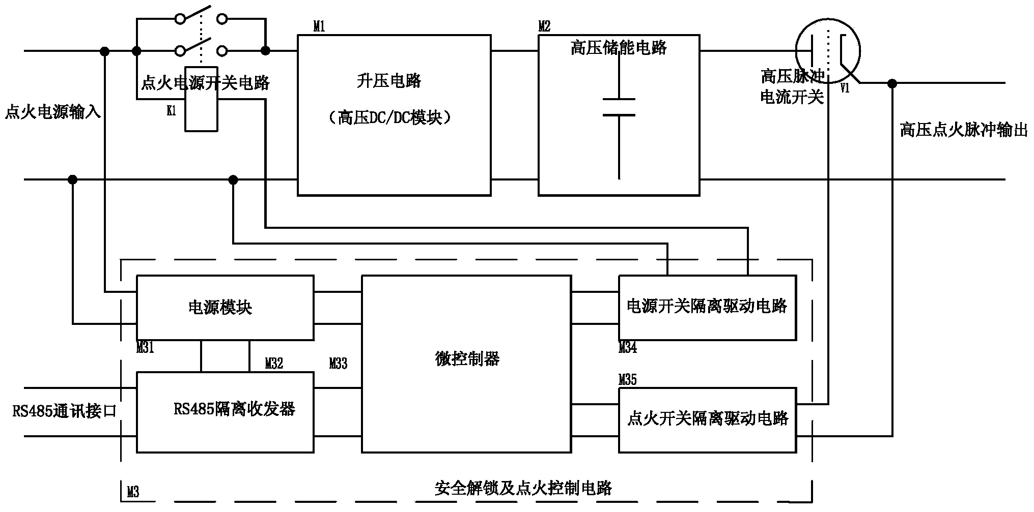
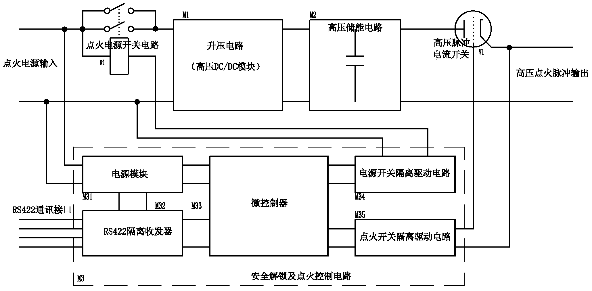
[0025] A high voltage ignition relay, such as figure 1 As shown, it is mainly composed of ignition power switch circuit, safety unlocking and ignition control circuit, boost circuit, high-voltage energy storage circuit, and high-voltage pulse current switch circuit. The input end of the ignition power switch circuit is connected with the external input signal of the ignition power supply. The output terminal of the ignition power switch circuit is connected with the input terminal of the boost circuit. The output end of the boost circuit is connected to the input end of the high voltage energy storage circuit. The output end of the high-voltage energy storage circuit is connected to the input end of the high-voltage pulse current switch circuit. The input end of the safety unlocking and ignition control circuit is connected to the ignition power input signal input from the outside, the control end of the safety unlocking and ignition control circuit is connected to the super...


PUM


Abstract

The invention discloses a high-voltage ignition relay which mainly consists of an ignition power supply switching circuit, a safety unlocking and ignition control circuit, a boosted circuit, a high-voltage energy storage circuit and a high-voltage pulse current switching circuit. The ignition power supply switching circuit, the boosted circuit, the high-voltage energy storage circuit and the high-voltage pulse current switching circuit are sequentially connected; an input end of the safety unlocking and ignition control circuit is connected with an externally input ignition power supply input signal; a control end of the safety unlocking and ignition control circuit is connected with a superior controller; a power switch drive output end of the safety unlocking and ignition control circuit is connected with a control end of the ignition power supply switching circuit; an ignition switch drive output end of the safety unlocking and ignition control circuit is connected with a control end of the high-voltage pulse current switching circuit. According to the high-voltage ignition relay, the safety of an ignition device can be improved, the sensitivity of an ignition system is reduced, and the high-voltage ignition relay has the characteristics of high operating reliability, small size, light weight and the like.

Description

technical field [0001] The invention relates to the technical field of relays, in particular to a high-voltage ignition relay and an operating method thereof. Background technique [0002] As a key component related to the safety and reliability of the weapon system, the ignition device directly affects the survivability and combat effectiveness of the entire weapon system. Under various harsh environmental conditions, on the one hand, it is required to ensure that the rated current pulse (generally working voltage is DC 27V) is provided to the ignition element (pyrotechnics) in a combat state; on the other hand, it is required to be in a safe (non-combat) state , to prevent ignition components from misignition under the action of radio frequency and static electricity. At present, the traditional pyrotechnic ignition circuit of the weapon system uses low voltage (DC 27V) and small current (10A) to ignite. Since the traditional pyrotechnic ignition circuit uses an electrome...

Claims


Application Information

Patent Timeline
Patent Type & Authority Applications(China)
IPC IPC(8): F42C19/12H02M9/00H02M3/335
Inventor 黄敏蒋端林何流军陆玉芳杨荣军
Owner G & A TECH
Why Eureka
Try Eureka