Structure and control method of direct-drive fiber-optic gyroscope stabilized platform

A fiber optic gyroscope and stable platform technology, which is applied in the direction of navigation through speed/acceleration measurement, can solve the problems of large transmission gear gap error, slow control response speed, and difficult to maintain accuracy, so as to avoid system errors, eliminate errors, improve The effect of precision and responsiveness

Active Publication Date: 2014-03-19
SOUTHEAST UNIV
View PDF4 Cites 19 Cited by
  • Summary
  • Abstract
  • Description
  • Claims
  • Application Information

AI Technical Summary

Problems solved by technology

[0006] Purpose of the invention: In order to overcome the deficiencies of the prior art, the present invention provides a direct-drive fiber optic gyroscope stable platform structure and its control method, using a direct-drive torque motor to overcome the high machining requirements of the existing stable platform system, difficult to maintain accuracy, The problem of large clearance error of transmission gear and slow control response speed

Method used


Image

  • Structure and control method of direct-drive fiber-optic gyroscope stabilized platform
  • Structure and control method of direct-drive fiber-optic gyroscope stabilized platform
  • Structure and control method of direct-drive fiber-optic gyroscope stabilized platform

Examples


Embodiment Construction

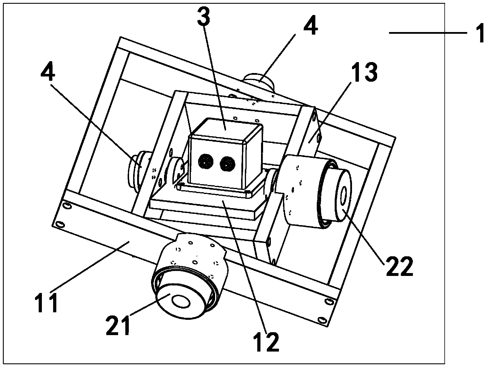
[0033] The present invention will be further explained below in conjunction with the accompanying drawings. Such as figure 1 As shown, a direct-drive fiber optic gyro stabilized platform structure includes a fiber optic gyro inertial measurement unit 3 and a group of grating rotary encoders 4; includes an outer frame 11, an inner frame platform 12, a middle frame 13, an outer frame torque motor 21 and an inner frame Frame torque motor 22; wherein the middle frame 13 is a roll frame, and the inner frame platform 12 is a pitch frame;

[0034] The outer frame torque motor 21 is installed on the outer frame 11, and the inner frame platform 12 is installed inside the middle frame 13;

[0035] The middle frame 13 is fixed with the outer frame torque motor 21 rotor, and the middle frame 13 rotates with the outer frame torque motor 21 rotor; the inner frame platform 12 is fixed with the inner frame torque motor 22 rotor, and the inner frame platform 12 rotates with the inner frame to...


PUM


Abstract

The invention discloses a structure and a control method of a direct-drive fiber-optic gyroscope stabilized platform. The structure is characterized in that a rectangular coordinate axes structure is adopted; an outer frame is a roll frame, and an inner frame platform is a pitch frame; an inertial measurement unit and a stabilized object are arranged on a platform of the inner frame platform; a platform framework is directly driven through a direct-drive moment motor. A control system is of the modular design and the double-central processing unit (CPU) combined design of a digital signal processor (DSP) and a singlechip computer, is stable, and is easy to operate. According to the structure and the control method, the problems of large machining and assembling difficulty of the existing stabilized platform system, difficulty in precision retention, large transmission gear clearance error, low control response speed and heavy load of a single-CPU multi-task control system are solved. The structure and the control method can be effectively applied to stabilization of airborne measurement equipment, ship-borne measurement equipment and vehicle-borne measurement equipment.

Description

technical field [0001] The invention relates to a stabilization system, in particular to a direct-drive fiber optic gyro stabilization platform structure and a control method thereof. Background technique [0002] The gyro-stabilized platform uses a gyroscope as a feedback element. Its main function is to isolate the angular motion of the carrier and make the axis of the stabilized object point to a specific orientation in the navigation coordinate system (such as the inertial coordinate system). When there is no disturbance moment acting on the supporting shaft of the load, the platform will always maintain its original angular position relative to the inertial space. When the load deviates from the original orientation due to the interference torque, the gyro sensitively measures the attitude angle or angular rate of the axis, and feeds back to the motor after passing through the control system. The compensation torque generated by the motor compensates the interference to...

Claims


Application Information

Patent Timeline
Patent Type & Authority Applications(China)
IPC IPC(8): G01C21/18
CPCG01C21/18
Inventor 程向红陆源朱倚娴
Owner SOUTHEAST UNIV
Why Eureka
Try Eureka