
Micro-nano scale dynamic coupling vibration single-point tracking measurement method

A dynamic coupling and tracking measurement technology, which is applied in the direction of measuring devices, scanning probe microscopy, instruments, etc., can solve the problem of inability to synchronize single-point tracking and measurement of inter-axial coupling micro-displacement oscillations of scanners, and achieve the elimination of image distortion, High precision, the effect of improving imaging precision

Inactive Publication Date: 2014-03-19
INST OF ELECTRICAL ENG CHINESE ACAD OF SCI
View PDF8 Cites 7 Cited by
  • Summary
  • Abstract
  • Description
  • Claims
  • Application Information

AI Technical Summary

Problems solved by technology

[0007] The purpose of the present invention is to overcome the shortcomings of the prior art that cannot synchronize single-point tracking to measure the coupling micro-displacement oscillation between the scanners, and propose a high-resolution single-point tracking measurement method for micro-nano scale dynamic coupling vibration

Method used


Image

  • Micro-nano scale dynamic coupling vibration single-point tracking measurement method
  • Micro-nano scale dynamic coupling vibration single-point tracking measurement method

Examples


Embodiment Construction

[0030] The present invention will be further described below in conjunction with the accompanying drawings and specific embodiments.

[0031] The steps of the inventive method are as follows:

[0032] 1) Determine the Z-direction vibration mode of the AFM piezoelectric scanner:

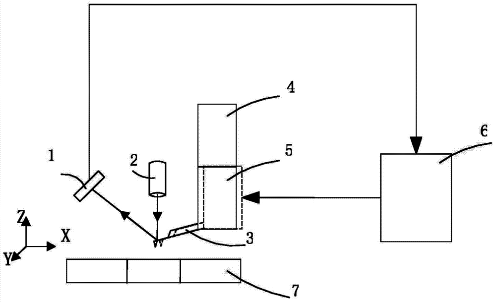
[0033] Such as figure 1 As shown, when the probe 3 is not in contact with the surface of the flatbed scanner 7, the atomic force microscope controller 6 controls the piezoelectric scanner 5 to drive the probe 3 to perform a reciprocating scanning movement of 100um in the X direction at a frequency of 100Hz, and the photoelectric sensor 1 senses the 3 The laser beam emitted from the laser light source 2 is reflected from the back, and the Z-direction vibration mode of the piezoelectric scanner 5 is obtained by measuring the Z-direction deflection of the probe 3 as S′(t)=0.027sin(200πt-2.750) um.

[0034] 2) Set the AFM automatic needle insertion process and the initial state of the probe:

[0035] Th...


PUM


Abstract

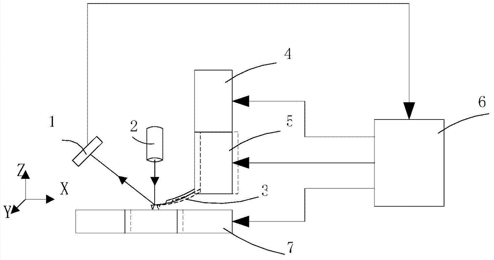
A micro-nano scale dynamic coupling vibration single-point tracking measurement method is provided. To begin with, under the condition that an AFM probe does not contact with the surface of a flat scanner, a piezoelectric scanner is driven to drive the probe to perform X-direction reciprocating scanning motion with a certain frequency and amplitude, and Z-direction deflection of the probe is recorded in real time so as to obtain a Z-direction vibration mode of the piezoelectric scanner; then, the probe is enabled to contact with the surface of the flat scanner through automatic probe entering process and scanner fine tuning, the flat scanner is controlled to be in synchronous movement with the probe in X direction and the Z-direction deflection of the probe is recorded so as to obtain a synchronous movement vibration mode of the piezoelectric scanner and the flat scanner; and at last, the recorded synchronous movement vibration mode and the vibration mode of the piezoelectric scanner are subtracted so that a Z-direction coupling vibration mode of the flat scanner at a certain position due to X-direction movement can be obtained.

Description

technical field [0001] The invention relates to a high-resolution single-point tracking measurement method for micro-nano scale dynamic coupling vibration based on a fast wide-range atomic force microscope. Background technique [0002] Atomic Force Microscope (AFM) fast scanning technology is a hot research direction with rapid development in recent years (T.Ando, ​​"High-speed atomic force microscopy coming of age", Nanotechnology, 2012, 23:06200-062028.). The improvement of the scan rate can not only reduce the scan time and improve the operating efficiency, but more importantly, it can make up for the lack of real-time observation of the dynamic changes of biological samples due to the slow scan rate (1 second / frame) of ordinary AFM. By further expanding the scanning range based on the AFM fast scanning technology, it is possible to measure and analyze large-scale biological samples such as living cells and fresh tissues with relatively complicated structures, large geom...

Claims


Application Information

Patent Timeline
Patent Type & Authority Applications(China)
IPC IPC(8): G01Q60/24
Inventor 陈代谢殷伯华韩立刘俊标林云生初明璋
Owner INST OF ELECTRICAL ENG CHINESE ACAD OF SCI
Learn More