Contactor electromagnetic system

An electromagnetic system and contactor technology, applied in the direction of electromagnetic relays, electromagnetic relay details, circuits, etc., can solve problems such as high production energy consumption, short service life, polluting the environment or poor effect of buffering vibration, etc., to achieve good buffering The effect of action

Active Publication Date: 2014-03-19
DELIXI ELECTRIC
View PDF7 Cites 4 Cited by
  • Summary
  • Abstract
  • Description
  • Claims
  • Application Information

AI Technical Summary

Problems solved by technology

[0009] For this reason, the technical problem to be solved by the present invention is to overcome the problems of complex buffer structure design, short service life, high production energy consumption, poor effect on environmen

Method used


Image

  • Contactor electromagnetic system
  • Contactor electromagnetic system
  • Contactor electromagnetic system

Examples


Embodiment 1

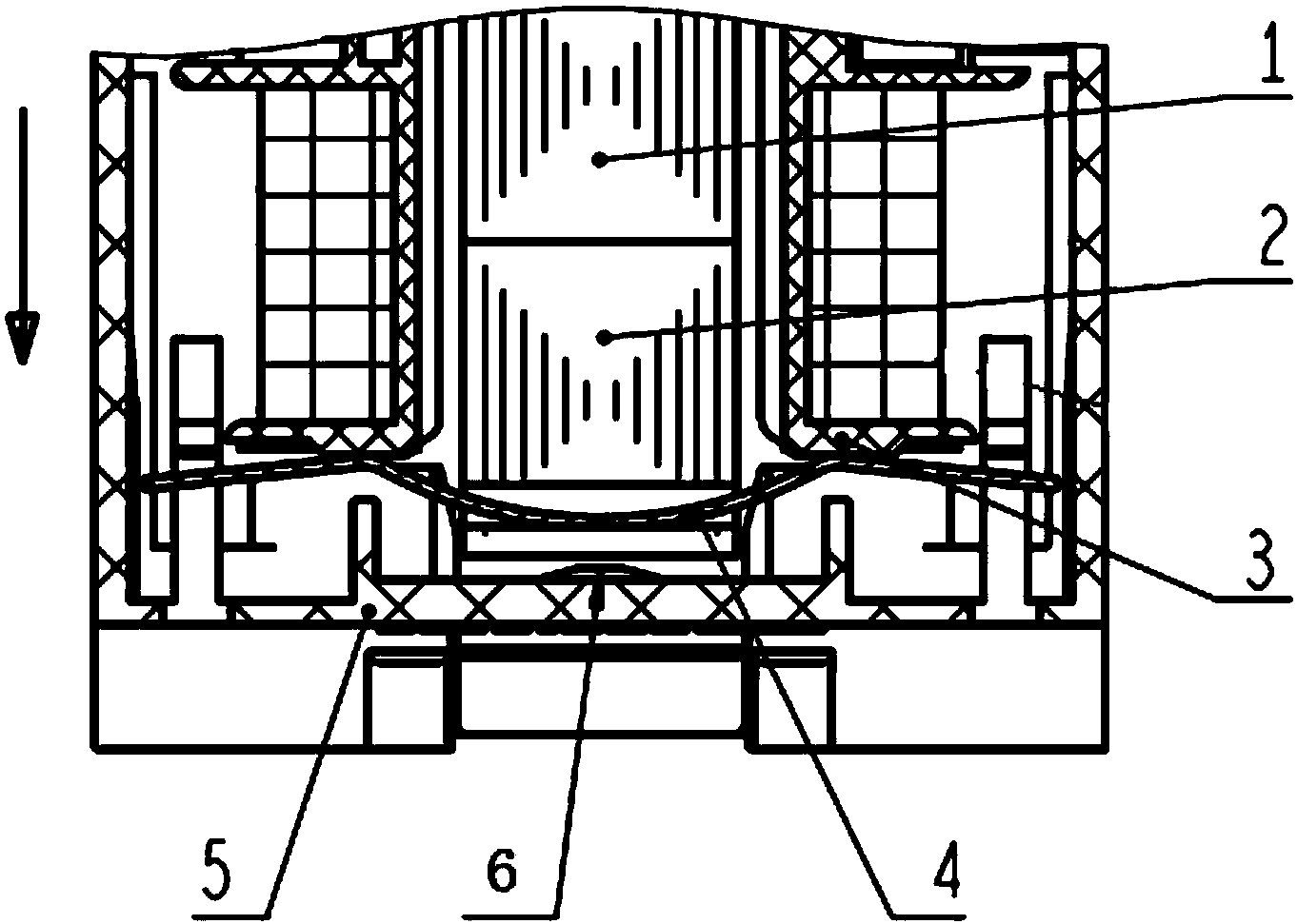
[0046] Such as figure 1 As shown, this embodiment provides a contactor electromagnetic system, including a base 5, a coil 3 disposed inside the base 5, a yoke 2, an armature 1, and an elastic buffer between the coil 3 and the base 5, and the coil is energized , a strong electromagnetic force is generated between the yoke 2 and the armature 1, and under the action of the electromagnetic force, the armature 1 and the yoke 2 are combined into one body and then move along the axial direction of the coil 3 hit the base, the elastic buffer buffers the vibration generated after the armature 1 and the yoke 2 hit the base 5; Vibration has a good buffering effect and will not cause a lot of pollution in the production process, such as figure 1 As shown, the yoke 2 of this embodiment is formed with installation holes penetrating from its two side walls, and the extension direction of the installation hole 21 is perpendicular to the axial direction of the coil 3, so that the extension ...

Embodiment 2

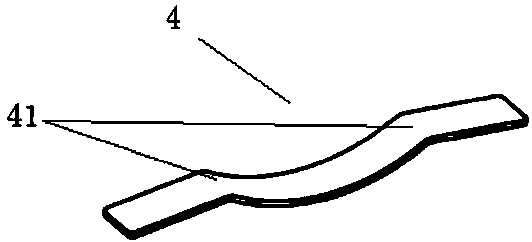
[0065] This embodiment provides a contactor electromagnetic system, which is a modification of Embodiment 1. The mounting holes 21 in this embodiment are formed into two, and are respectively formed between two adjacent vertical portions 23 On the horizontal part 22 between, the size of the two installation holes 21 is the same, and each of the installation holes 21 is inserted with the leaf spring 4 as described in the first embodiment.

Embodiment 3

[0067] This embodiment provides a contactor electromagnetic system, which is a modification of Embodiment 1 and Embodiment 2. In this embodiment, both ends of the leaf spring 4 are fixed relative to the base 5 .

[0068] Specifically, both ends of the leaf spring 4 are respectively fixed on the ends of the coil 3 that are opposite to the side wall of the base 5 that is hit.

[0069] As a modification of fixing the two ends of the leaf spring 4, the two ends of the leaf spring 4 in this embodiment can also be fixed on the two side walls of the base 5, or the base 5 The two ends of the leaf spring 4 corresponding to the impacted side walls are respectively formed with bosses protruding towards the two ends of the leaf spring 4, and the two ends of the leaf spring 4 can be fixed on the two ends of the leaf spring 4. on the boss.


PUM


Abstract

The invention provides a contactor electromagnetic system which comprises a base, a coil, a magnetic yoke, an armature and an elastic buffering piece, wherein the coil, the magnetic yoke and the armature are arranged in the base, the elastic buffering piece is disposed between the coil and the base. A mounting hole is formed on the magnetic yoke and the extending direction of the mounting hole is perpendicular to the axial direction of the coil. The elastic buffering piece is a sheet spring, the middle of the sheet spring is an arc which is inserted in the mounting hole and protrudes towards an impacted part of the base, and the arc top is deformed due to compression of the wall of the mounting hole so as to buffer vibration of the armature and the magnetic yoke when the magnetic yoke and the armature bounce in opposite directions after impacting the base. According to the invention, vibration of the armature and the magnetic yoke can be quickly attenuated and stopped due to large energy loss of the sheet spring in the compression and elastic recovery processes, energy loss generated when the armature and the magnetic yoke impact the base and frictional energy dissipation generated when the two ends of the sheet spring slide in a reciprocating mode on the base or the coil in the compression and elastic recovery processes of the sheet spring.

Description

technical field [0001] The invention relates to a contactor, in particular to a contactor electromagnetic system for buffering the vibration of an armature and a magnetic yoke after attraction, and belongs to the technical field of low-voltage electrical appliances. Background technique [0002] A contactor is a non-manually operated mechanical switching device that can carry and frequently switch on and off currents under normal circuit conditions. The contactor consists of an electromagnetic system (armature, yoke and electromagnetic coil), a contact system and an arc extinguishing device. [0003] Contactor electromagnetic system, when the coil is energized, the yoke is magnetized, electromagnetic attraction is generated between the yoke and the armature, the electromagnetic attraction overcomes the reaction force of the reaction spring and the armature is attracted to the yoke, and the contact is driven when the armature and the yoke are closed The system is closed, so ...

Claims


Application Information

Patent Timeline
IPC IPC(8): H01H50/36H01H50/30H01H50/02
CPCH01H50/305H01H50/36
Inventor 蔡洪洲靳海富张红伟
Owner DELIXI ELECTRIC
Why Eureka
Try Eureka