Double stator high power density flux switching permanent magnet motor

A technology of high power density and magnetic flux switching, applied in motors, electric vehicles, electrical components, etc., can solve the problems of difficult installation of permanent magnets, difficult heat dissipation of permanent magnets, and poor structural reliability, so as to reduce the risk of irreversible demagnetization and reduce costs. and weight, benefits for production and installation

Active Publication Date: 2016-07-20
NANJING UNIV OF AERONAUTICS & ASTRONAUTICS
View PDF3 Cites 0 Cited by
  • Summary
  • Abstract
  • Description
  • Claims
  • Application Information

AI Technical Summary

Problems solved by technology

This structure has the following disadvantages: First, because the permanent magnet is placed on the rotor, it is difficult to install the permanent magnet, and its structural reliability is poor in high-speed motion, and there is a risk of falling off; secondly, when the permanent magnet is placed on the rotor between the double stators, Permanent magnets are not easy to dissipate heat, and there is a risk of high temperature demagnetization
The double-stator structure obtained directly from the flux-switching motor has the common advantages of the double-stator motor and the flux-switching motor, but because the rotor is a salient pole structure, in the double-stator structure, the height of the teeth of the rotor and the height of the magnetic yoke The height is approximately twice that of the unilateral flux switching motor, so the motor has a large rotor inertia, large volume, large iron loss, low power density, and low efficiency

Method used


Image

  • Double stator high power density flux switching permanent magnet motor
  • Double stator high power density flux switching permanent magnet motor
  • Double stator high power density flux switching permanent magnet motor

Examples


Embodiment 1

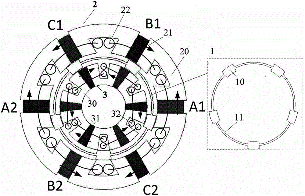
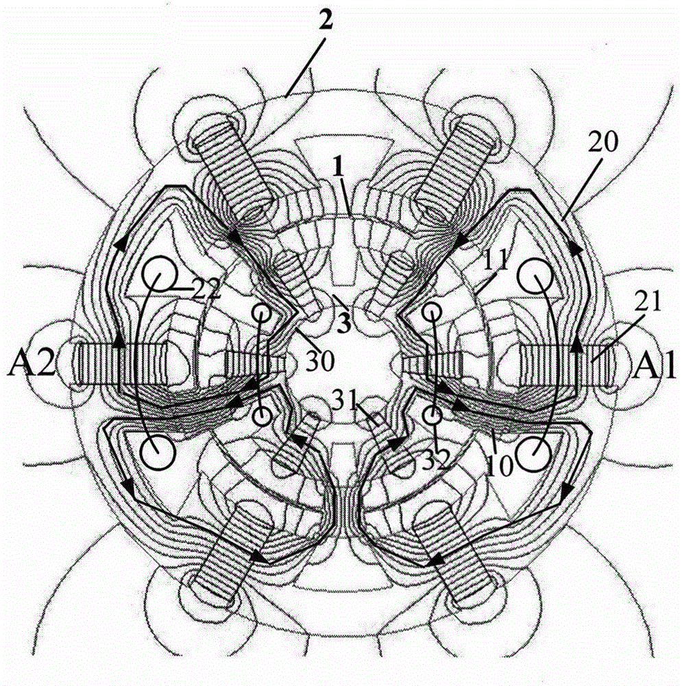
[0028] Such as figure 1 As shown, the present invention includes a double-sided stator and a rotor, with an air gap between the rotor 1 and the outer stator 2 and inner stator 3 . The outer stator 2 includes 2km=6 U-shaped magnetic permeable blocks 20, 2km=6 permanent magnets 21 and 2km=6 sets of concentrated windings 22, k=1, m=3 are all positive integers, and m represents the number of motor phases. The embodiment is a three-phase motor; each permanent magnet 21 is sandwiched between two adjacent U-shaped magnetic blocks 20, and the concentrated winding 22 is arranged in the groove of the U-shaped magnetic block and encases the permanent magnets 21; adjacent permanent magnets The magnets are alternately magnetized tangentially. The inner stator 3 also includes 6 U-shaped magnetic blocks 30, 6 permanent magnets 31 and 6 sets of concentrated windings 32. The radial axes of the inner stator 3 and the magnetic blocks of the outer stator 2 coincide with each other, and the magne...

Embodiment 2

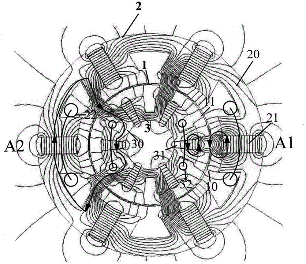
[0034] Figure 4 It is a three-phase double-stator high power density flux switching permanent magnet motor. The outer stator 2 of the present embodiment comprises 2km=12 pieces of U-shaped magnetic permeable blocks 20, 2km=12 pieces of permanent magnets 21 and 2km=12 sets of concentrated windings 22, get k=2, m=3, because the rotor magnetic permeable blocks 10 The number Nr=2km±n (n / m is not an integer), when n=1 and 2, Nr can be 10,11,13,14, and present embodiment gets Nr=2km+n=14 (n= 2), m represents the number of motor phases, and this embodiment is also a three-phase motor; each phase winding in the outer stator 2 in this embodiment is composed of four concentrated windings A1, A2, A3 and A4 connected in series or in parallel. The relative positions of concentrated windings A1 and A3 to rotor 1 are the same, and the relative positions of A2 and A4 to rotor 1 are also the same, but the relative positions of A1 and A3 and A2 and A4 to rotor 1 differ from each other by half...

Embodiment 3

[0036] Figure 5 Also for a three-phase dual-stator high power density flux switching permanent magnet motor. The difference between this embodiment and the motor of Embodiment 2 is that the number of magnetic conductive blocks of the rotor 1 is Nr=2km+n=13 (n=1), k=2, m=3, and this embodiment is also a three-phase motor. Each phase winding in the outer stator 2 is composed of four concentrated windings A1, A2, A3 and A4 connected in series or in parallel. The relative positions of concentrated windings A1 and A3 and the rotor differ by half a rotor 1 pole pitch, and the relative positions of A2 and A4 and the rotor also differ by half a rotor 1 pole pitch, but the relative positions of A1 and A3 and A2 and A4 and rotor 1 The positions are relatively close. When the concentrated windings A1, A2, A3 and A4 are connected in series to form the A-phase winding, the amplitude of the back EMF of the A-phase winding is slightly less than four times the fundamental amplitude of the c...


PUM


Abstract

The invention provides a double-stator high-power-density flux switching permanent magnet motor. The double-stator high-power-density flux switching permanent magnet motor comprises an outer stator, an inner stator and a rotor, and air gaps exist between the rotor and the stators. The rotor is composed of magnetic blocks, the magnetic blocks are evenly distributed in space and can be arranged at intervals or connected into a whole through connecting bridges; the outer stator is composed of U-type magnetic blocks, tangential magnetized permanent magnets and concentrated windings; every permanent magnet is clamped between the corresponding two neighboring U-type magnetic blocks, and the concentrated windings are arranged inside the grooves of the U-type magnetic blocks and house the permanent magnets; the neighboring permanent magnets magnetize alternately each other in the tangent direction; the radial axises of U-type magnetic blocks of the inner stator and the outer stator mutually coincide, and the magnetic teeth of the U-type magnetic blocks of the inner stator and the outer stator are opposite to each other; the magnetizing directions of the permanent magnets of the inner stator and the outer stator, which are identical in spatial position, are inverse, and the concentrated windings of the inner stator and the outer stator, which are identical in spatial position, are on the same phase. Compared with the prior art, the double-stator high-power-density flux switching permanent magnet motor omits rotor magnetic yokes, reduces the size of the rotor and the consumption of iron, improves the power density and the efficiency and can be applied to power systems such as wind power generation, electric vehicles and ships and warships.

Description

technical field [0001] The invention relates to a double-stator high-power-density magnetic flux switching permanent magnet motor, which belongs to the technical field of motor manufacturing. Background technique [0002] With the development of industry, permanent magnet motors have been widely used in wind power generation, electric vehicles, ships and other fields. In high-power drive and power generation systems, the volume of the motor is large. In order to increase the power density of the motor, enhance the power distribution capability of the system, and reduce costs, the motor can adopt a double-stator structure. Since the armature winding and the permanent magnet of the traditional permanent magnet synchronous motor are respectively placed in the stator or the rotor, when a double stator structure is adopted, the permanent magnet is generally placed in the rotor, and the rotor is placed in the middle of the double stator. This structure has the following disadvant...

Claims


Application Information

Patent Timeline
Patent Type & Authority Patents(China)
IPC IPC(8): H02K16/04
CPCY02T10/64
Inventor 曹瑞武黄文新
Owner NANJING UNIV OF AERONAUTICS & ASTRONAUTICS
Why Eureka
Try Eureka