A Finite Arbitrary Frequency Difference Reflection Control Method for Microwave Signals

A control method, microwave signal technology, applied in the direction of amplitude to angle modulation and conversion, which can solve the problems of limited simulation range, continuous cable and cable, discontinuous frequency difference, etc.

Active Publication Date: 2016-05-25
CHINA ELECTRONIS TECH INSTR CO LTD
View PDF5 Cites 0 Cited by
  • Summary
  • Abstract
  • Description
  • Claims
  • Application Information

AI Technical Summary

Problems solved by technology

[0004] First, the main disadvantage of the equivalent length cable box simulation scheme is that the frequency difference is not continuous because the cables cannot be continuous at any length, and because the length of the cable is limited, the simulation range is limited. of
The second is to adopt the scheme of mixer + DDS. Multi-level frequency conversion not only leads to the complexity of implementation, but also introduces spurious signals that interfere with the accuracy of measurement. Currently, DDS needs multiple frequency multiplications due to frequency limitations, resulting in spurious More, and the phase noise itself is poor. After frequency doubling, the phase noise will be further deteriorated, which will not meet the test requirements when the frequency difference is small.
Moreover, the complexity of the implementation circuit is difficult to meet the needs of field testing, and the power consumption is relatively large.

Method used


Image

  • A Finite Arbitrary Frequency Difference Reflection Control Method for Microwave Signals

Examples


Embodiment 1

[0027] In the present invention, the input signal is coupled out one way, and after wave detection, it is collected by DAC, and then after data processing, power detection is performed. If the power is large, a corresponding voltage is inserted through DAC, and attenuated by a voltage-controlled attenuator. , then remain unchanged, and finally adjusted to match the suitable power range of the IQ modulator, and used as the local oscillator signal input of the IQ modulator. The required frequency difference digital signal is generated by FPGA or an equivalent digital circuit. After digital-to-analog conversion by DAC, it is divided into sin signal and cos signal. After multiplication in the IQ modulator, a single sideband signal and carrier and image frequency signals are suppressed to a certain extent. The signal output by the IQ modulator passes through a multi-stage power attenuator and an amplitude stabilization loop, and is output after being adjusted to the power required ...

Embodiment 2

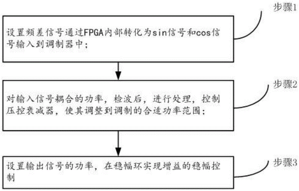
[0039] On the basis of above-mentioned embodiment, further as figure 1 As shown, a limited arbitrary frequency difference reflection control method for microwave signals is provided, which includes the following steps:

[0040] Step 1, set the frequency difference signal to be converted into a sin signal and a cos signal through the FPGA and input to the IQ modulator;

[0041] Step 2, after detecting the coupled power of the input signal, process it, and control the voltage-controlled attenuator to adjust it to a suitable power range for modulation;

[0042] In step 3, the power of the output signal is set, and the amplitude stabilization control of the gain is realized in the amplitude stabilization loop.

[0043]Step A1 is also performed after the step 1: the amplitude, phase and delay setting of the two-way signals of the IQ modulator are calibrated by adjusting the digital value through the FPGA.

[0044] In the step 1, the sin signal and the cos signal are multiplied in...


PUM


Abstract

The invention provides a limited random frequency different reflection control method of a microwave signal. The limited random frequency different reflection control method of the microwave signal comprises the following steps: step 1, setting a frequency different signal, converting the frequency difference signal to a sin signal and a cos signal when the frequency different signal passes in a FPGA (Field Programmable Gata Array), and inputting the sin signal and the cos signal to a modulator; step 2, performing demodulation on a coupling power of an input signal, then processing the coupling power, controlling a voltage-controlled attenuator, and adjusting the voltage-controlled attenuator to a proper power range; step 3, setting a power of an output signal to realize stable amplitude control on a gain at an amplitude stabilizing ring. Due to the adoption of the limited random frequency different reflection control method, the offset of a carrier wave and the suppression of an image frequency can be effectively suppressed by a calibration modulator; a spurious signal is reduced, so that the phase noise worsening degree is constant in the process of changing the frequency in a whole channel, and the reliability is realized due to a small frequency difference.

Description

technical field [0001] The invention belongs to the technical field of microwave signal control, and in particular relates to a limited arbitrary frequency difference reflection control method of microwave signals. Background technique [0002] At present, any frequency difference adjustment can be applied to devices such as radio altimeter simulators, which are important instruments for testing the accuracy of airborne radio altimeters, and can be widely used in military and civilian multi-arms and multi-aircraft altimeter inspections. The radio altimeter is an important measuring element for various aircraft and missiles, and its performance determines the control quality of the longitudinal flight path of the aircraft. Its working principle is to track the altimeter output scanning signal in real time, generate a signal with a fixed frequency difference from the scanning signal through frequency synthesis, and output it to the altimeter receiver as feedback. Any frequenc...

Claims


Application Information

Patent Timeline
Patent Type & Authority Patents(China)
IPC IPC(8): H03C3/40
Inventor 董建涛薛沛祥刘磊缪国锋李墩泰苏杰
Owner CHINA ELECTRONIS TECH INSTR CO LTD
Why Eureka
Try Eureka