
Method for producing a cylinder liner surface and cylinder liner

A cylinder liner and working surface technology, applied in the direction of cylinder, cylinder head, metal material coating process, etc., can solve the problems of material cost, manufacturing process cost disadvantage and influence, and achieve the effect of less coating material consumption and effective protection

Inactive Publication Date: 2014-03-19
MAHLE INT GMBH
View PDF4 Cites 6 Cited by
  • Summary
  • Abstract
  • Description
  • Claims
  • Application Information

AI Technical Summary

Problems solved by technology

However, this has an adverse effect on material costs and manufacturing process costs

Method used


Image

  • Method for producing a cylinder liner surface and cylinder liner
  • Method for producing a cylinder liner surface and cylinder liner

Examples


Embodiment Construction

[0017] Embodiments of the present invention will be described in detail below.

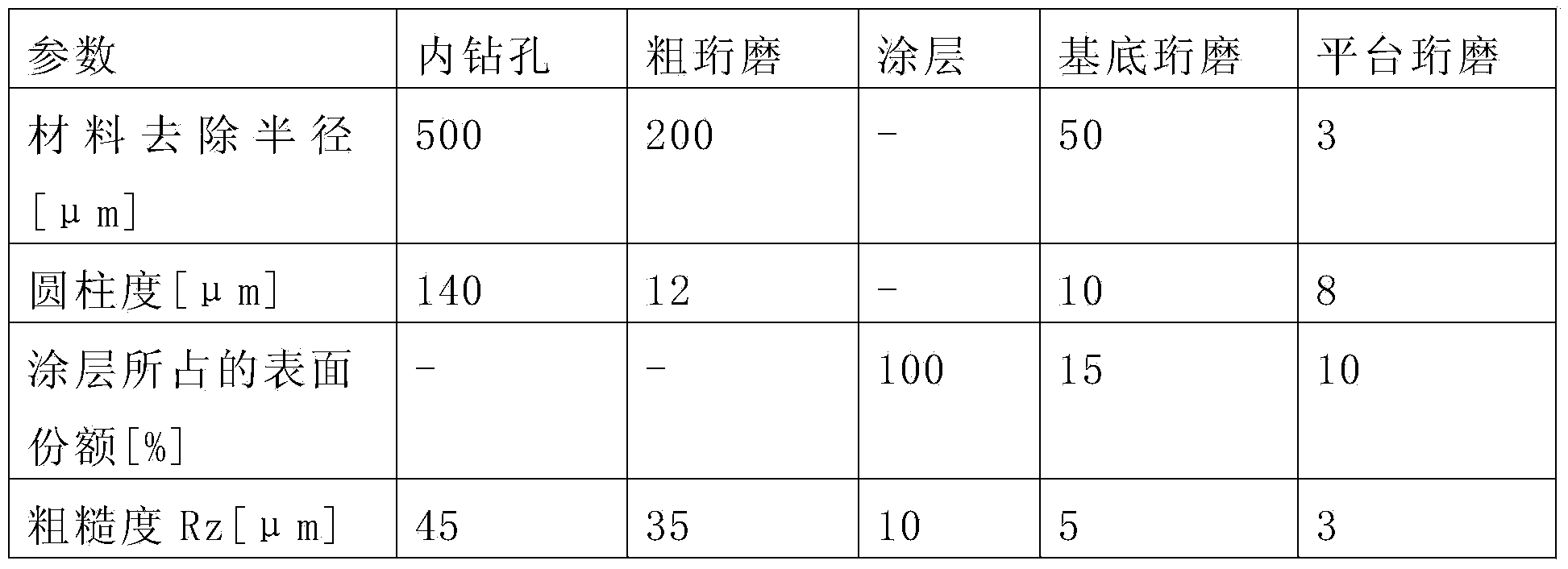
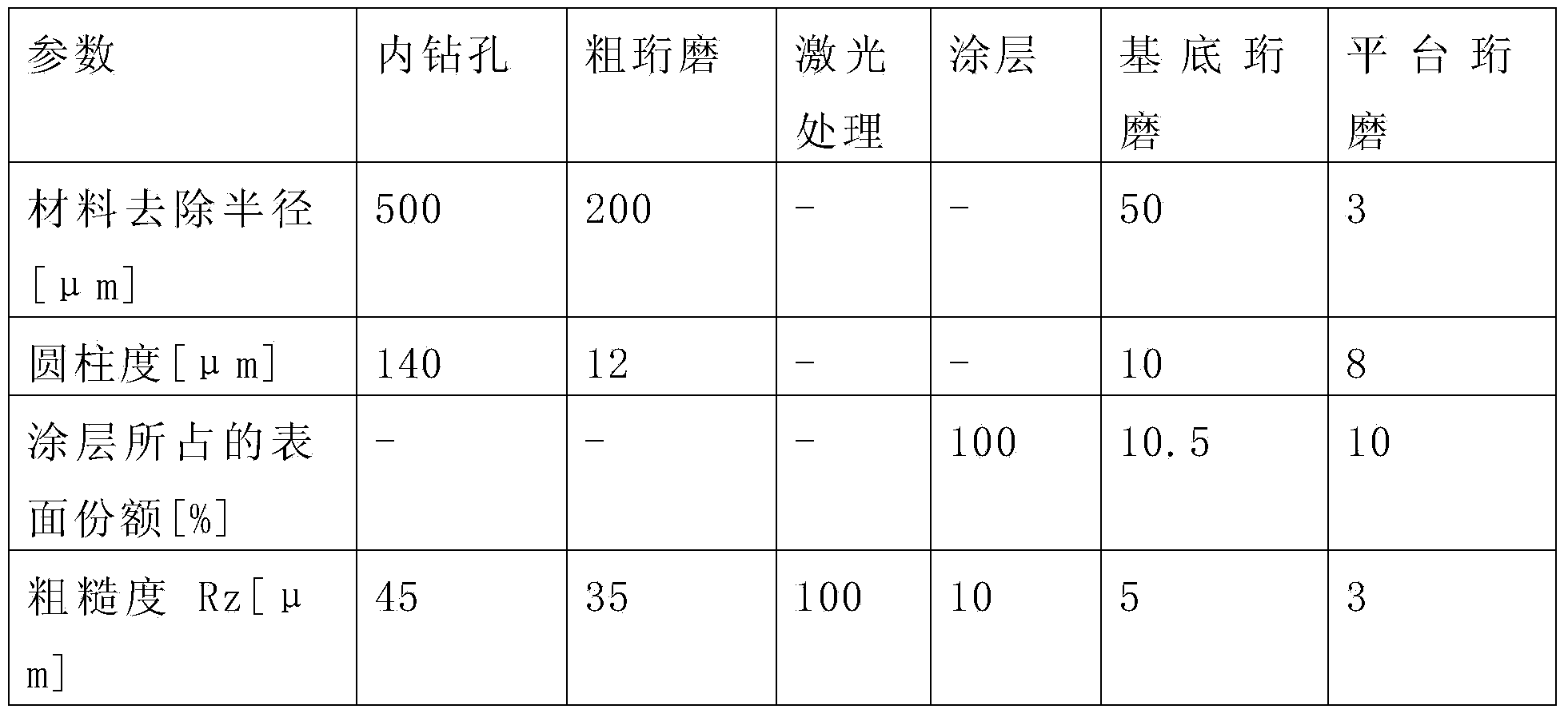
[0018] According to the invention, the inner surface of the cylinder liner is machined from a commercially available cast iron material. For this purpose, the internal bore is firstly drilled in a known manner by means of a drilling tool. For this purpose, defined dimensions, defined cylindricity and roughness are provided for the inside diameter. This prepares the inner surface of the cylinder liner for the subsequent process steps.

[0019] In a subsequent process step, the inner surface of the cylinder liner is machined by rough honing using a honing tool, the honing stones of the honing tool grinding away material from the inner surface of the cylinder liner. This improves the accuracy of the inner diameter in terms of size, cylindricity and roughness. At the same time, defined depressions (“honing grooves”) are introduced into the inner surface of the cylinder liner. The number, depth and...


PUM

PropertyMeasurementUnit
diameteraaaaaaaaaa

Abstract

The invention relates to a method for producing a cylinder liner surface for a cylinder crankcase of an internal combustion engine, characterised by the following method steps: (a) preliminary honing of the inner surface of a cylinder liner consisting of a cast iron material to form depressions in the surface; (b) application of a coating material containing zinc to said honed surface; (c) final honing of the coated surface in such a way that the coating material containing zinc remains only in the depressions formed by the preliminary honing.

Description

technical field [0001] The invention relates to a method for producing a cylinder running surface and a cylinder liner of a cylinder block crankcase of an internal combustion engine. Background technique [0002] Cylinder liners are usually made of steel or cast iron materials. But cylinder liners made of cast iron material are susceptible to corrosion. It is known, however, that the running surface of the cylinder liner is galvanically provided with a corrosion-resistant and wear-resistant coating, for example based on chromium. However, this has an adverse effect on material costs as well as manufacturing process costs. Contents of the invention [0003] It is therefore the object of the invention to increase the corrosion resistance of cylinder liners made of cast iron material. Furthermore, there is a need to reduce material costs and manufacturing costs. [0004] The implementation solution is a method with the following process steps: (a) pre-honing the inner sur...

Claims


Application Information

Patent Timeline
Patent Type & Authority Applications(China)
IPC IPC(8): C23C24/04C23C4/02C23C4/08C23C4/18F02F1/20C23C26/00
CPCF02F1/20C23C24/04C23C26/00C23C4/08F02F1/004C23C4/02C23C4/18
Inventor 乌尔里希·比朔夫贝格尔斯特凡·盖泽尔曼
Owner MAHLE INT GMBH
Learn More