Runner for a hydraulic machine, hydraulic machine provided with such a runner, and power-conversion equipment including such a hydraulic machine

A technology of hydraulic machinery and runners, which is applied in the fields of hydraulic machinery and mixed-flow runners, and can solve the problems of not being able to improve the stability of the rotation speed of the runners

Active Publication Date: 2014-03-19
GE RENEWABLE TECH
View PDF9 Cites 12 Cited by
  • Summary
  • Abstract
  • Description
  • Claims
  • Application Information

AI Technical Summary

Problems solved by technology

Such geometric features do not improve the stability of the rotati

Method used


Image

  • Runner for a hydraulic machine, hydraulic machine provided with such a runner, and power-conversion equipment including such a hydraulic machine
  • Runner for a hydraulic machine, hydraulic machine provided with such a runner, and power-conversion equipment including such a hydraulic machine
  • Runner for a hydraulic machine, hydraulic machine provided with such a runner, and power-conversion equipment including such a hydraulic machine

Examples


Embodiment Construction

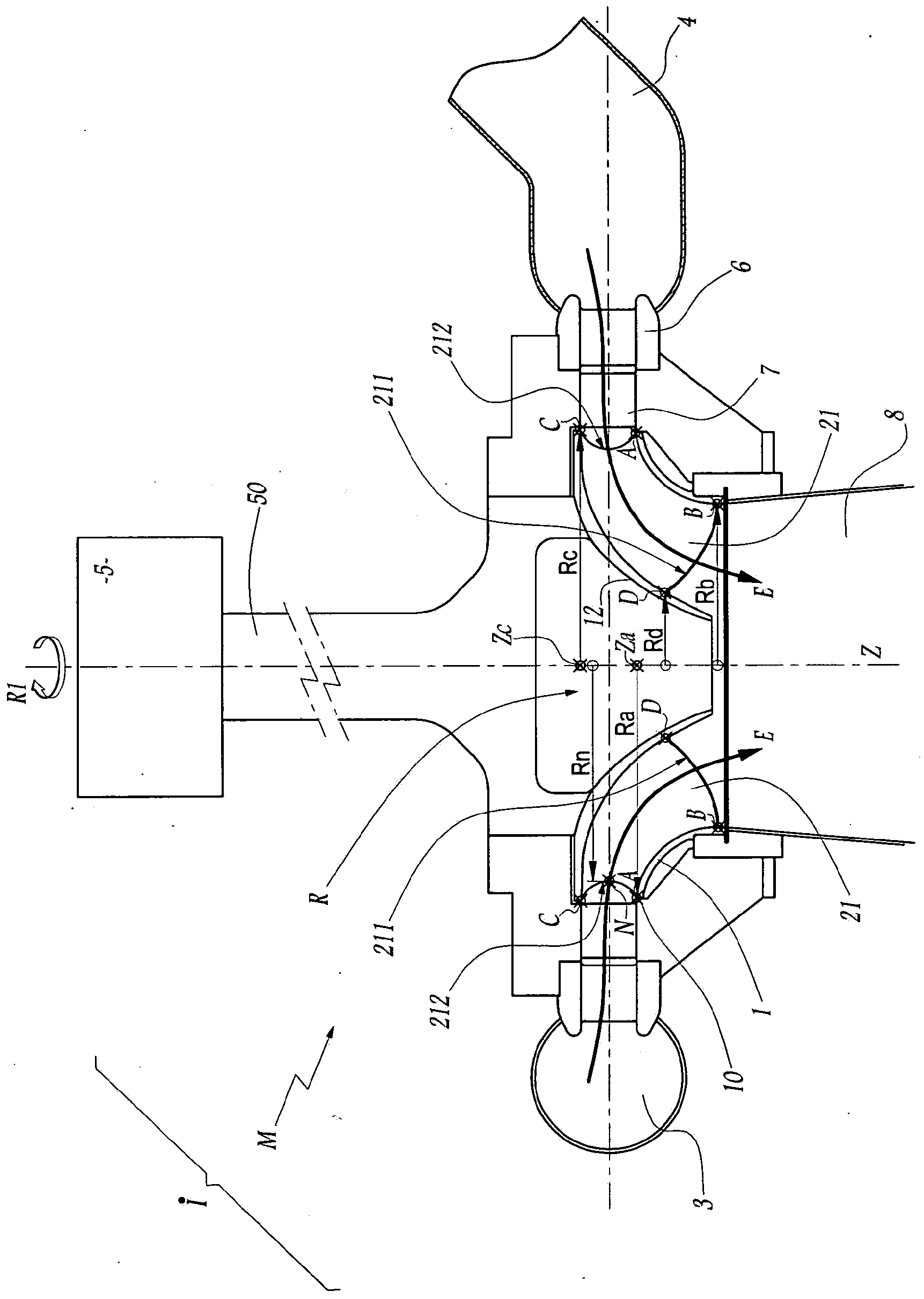
[0049] image 3 The device I shown in includes a reversible hydraulic machine M, which is a Francis pump-turbine (Francis pump-turbine), using a waterproof cloth to supply water to the runner R3 of the Francis pump-turbine, When the machine M works in the water turbine mode, a forced conduit 4 is drawn. In operation, the wheel 200 rotates about a vertical axis of rotation Z. When the machine M is operating in water turbine mode, the runner 200 rotates around the axis Z in a direction of rotation R1 which is clockwise when viewing the runner R from above. In order to generate electricity in turbine mode, the machine M is connected to an alternator 5 via a transmission shaft 50 rotating about an axis Z. Between the tarpaulin 3 and the runner R are arranged leading vanes and directional vanes 7 whose function is to guide the water flow E coming from the duct 4 and intended to flow through the runner R to the drain duct 8 . Since the guide vanes 7 make it possible to adjust the...


PUM


Abstract

The invention relates to a Francis runner (200) for a hydraulic machine, comprising: a wheel (1), which is rotationally symmetrical about an axis of rotation (Z) of the runner (200); a crown (12); and a plurality of inwardly curved vanes (21), each of which has a peripheral edge (212). The peripheral edge (212) of at least one of the vanes is curved, the concavity thereof facing toward the outside of the runner (200). The maximum value of the distance measured between any point on the peripheral edge (202) and a straight line passing through a first connection point between the peripheral edge (212) and the wheel (1), and through a second connection point between the peripheral edge (212) and the crown (12), is at an intermediate point on the peripheral edge (212). The radius (Rn) from the intermediate point (N) is strictly smaller than the radius (Ra) from the first connection point (A). The radius (Rn) from the intermediate point (N) is strictly smaller than the radius (Rc) from the second connection point (C).

Description

technical field [0001] This invention relates to a Francis runner for hydraulic machines through which a forced flow of water passes. When the machine is a water turbine, such water flow has the effect of driving the runner to rotate; and when the machine is a pump, such water flow is generated by this rotation. The invention also relates to a hydraulic machine equipped with such a runner. In another aspect, the invention relates to an energy conversion device comprising such a hydraulic machine. Background technique [0002] Typically, the means for converting water energy into electrical energy comprises a hydraulic machine operating in turbine mode and passed through by a forced flow of water at a speed controlled by a distributor. The runner of the water turbine rotates a drive shaft connected to an alternator. In order to connect the alternator to the grid, the rotational speed of the water turbine must be stabilized such that the frequency of the electrical signal a...

Claims


Application Information

Patent Timeline
IPC IPC(8): F03B3/02F03B3/12
CPCF03B3/02F03B3/121F03B3/125Y02E10/223F05B2250/712F05B2240/30F03B3/12Y02E10/20F03B3/06
Inventor S·拉维涅J-B·乌德兰C·贝拉尔
Owner GE RENEWABLE TECH
Why Eureka
Try Eureka