Method for controlling adsorption heat pump, information processing system, and control device

An information processing system and adsorption heat pump technology, applied in the direction of adsorption machines, refrigerators, refrigeration components, etc., can solve the problem of data center consumption and other issues

Inactive Publication Date: 2014-03-19
FUJITSU LTD
View PDF5 Cites 10 Cited by
  • Summary
  • Abstract
  • Description
  • Claims
  • Application Information

AI Technical Summary

Problems solved by technology

[0004] However, about 40% of all power consumption in data centers is consumed by air conditioning equipment

Method used


Image

  • Method for controlling adsorption heat pump, information processing system, and control device
  • Method for controlling adsorption heat pump, information processing system, and control device
  • Method for controlling adsorption heat pump, information processing system, and control device

Examples


Embodiment approach )

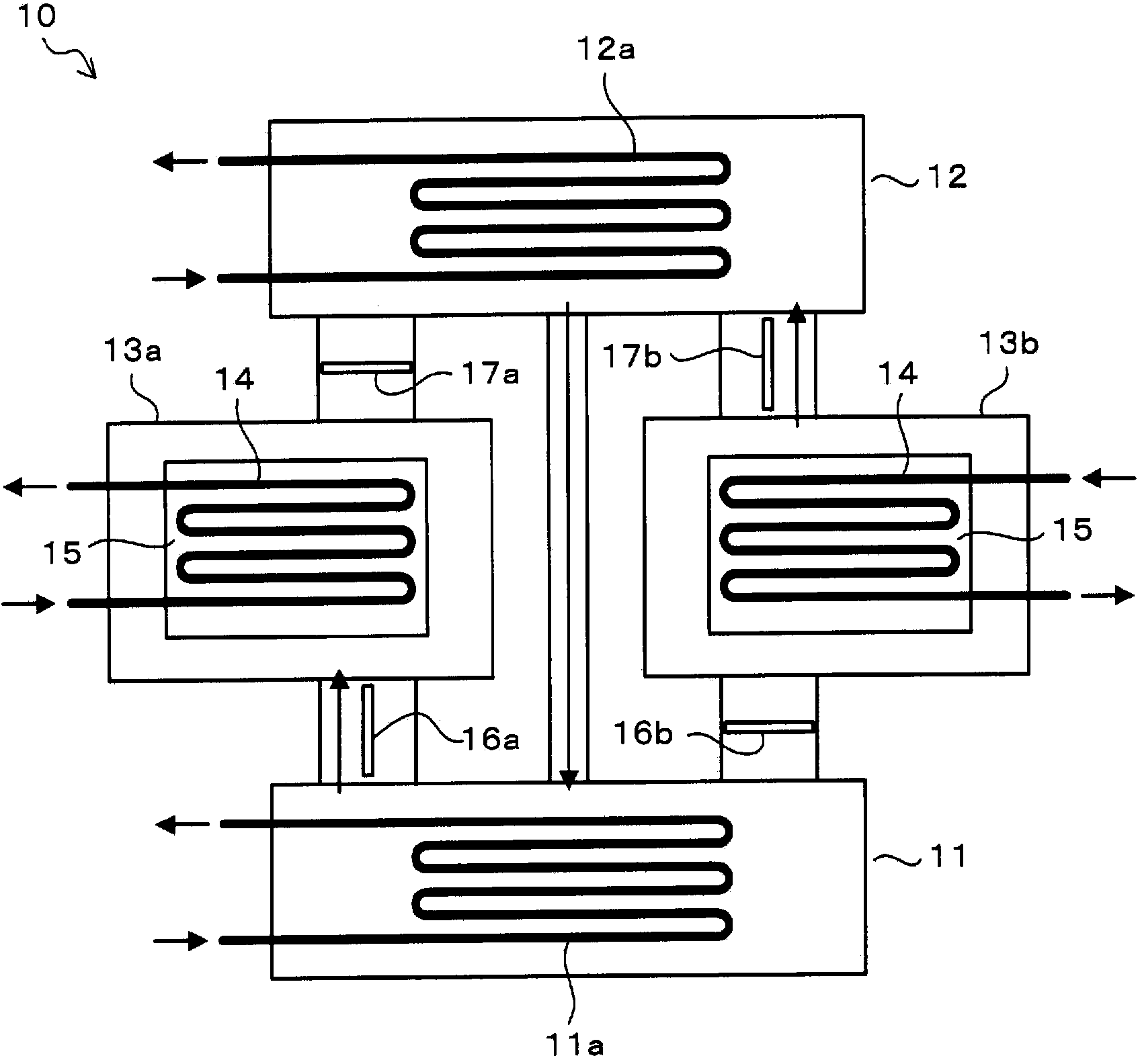
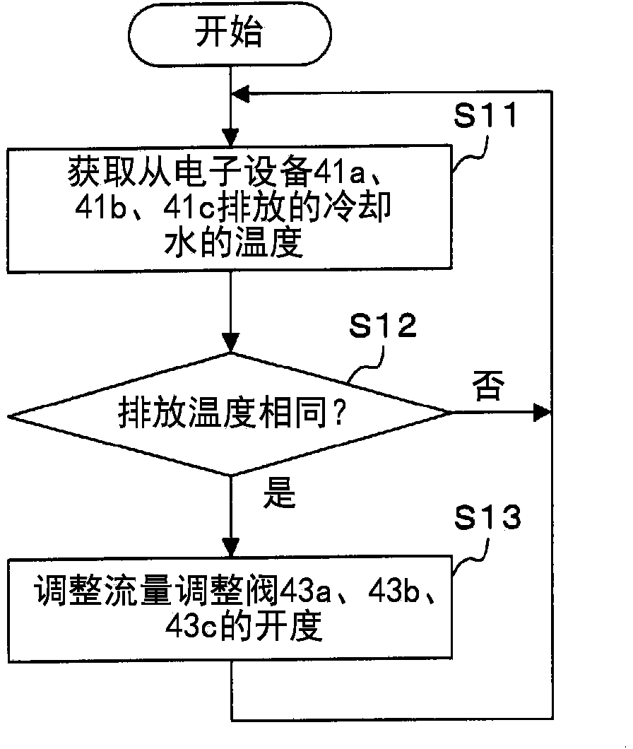
[0050] figure 2 It is a schematic diagram explaining the control method of the adsorption-type heat pump of embodiment. In addition, this embodiment also refers to figure 1 to explain.

[0051] Such as figure 1 As shown, the adsorption heat pump 10 has an evaporator 11, a condenser 12, and adsorbers 13a, 13b. A cooling water coil 11 a is arranged in the evaporator 11 , and a cooling water coil 12 a is arranged in the condenser 12 . Moreover, the heat transfer pipe 14 and the adsorbent 15 are respectively arrange|positioned in the adsorber 13a, 13b.

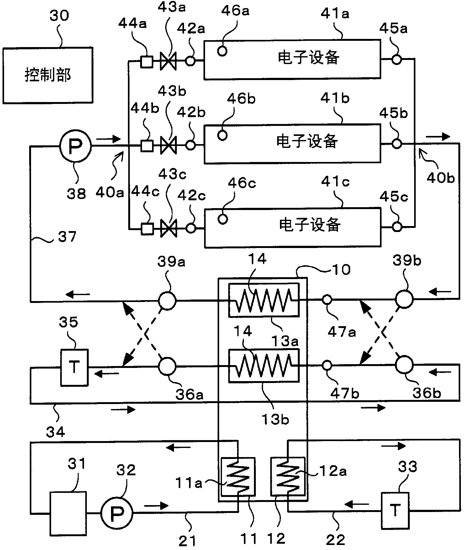
[0052] Such as figure 2 As shown, the cooling water coil 11 a of the evaporator 11 of the adsorption heat pump 10 is connected to the evaporator cooling water flow path 21 . A cooling water storage tank 31 for storing cooling water and a pump 32 for circulating cooling water between the cooling water storage tank 31 and the evaporator 11 are provided on the evaporator cooling water passage 21 . The cooling water stored in...

experiment example )

[0103] Next, results obtained by experimentally confirming the effect of the method for controlling the adsorption heat pump according to the embodiment will be described.

[0104] Figure 9 It is a schematic diagram explaining the apparatus used in the experiment. in the Figure 9 in, right with figure 2 Identical components are marked with the same reference numerals. A refrigeration unit 51 is arranged on the evaporator cooling water flow path 21 to replace figure 2 The cooling water storage tank and the pump 32 are illustrated. Assuming that the set temperature TL of the refrigeration unit 51 is 18°C, the set temperature T of the refrigeration units 33 and 35 M is 25°C.

[0105] In addition, in the experiment, one server 53 (RX300S6 manufactured by Fujitsu Corporation) and two analog servers 54 were used as electronic devices. Two CPUs 55 are installed on the server 53 , and cooling plates are respectively installed on the two CPUs 55 , and heat medium is discharg...


PUM


Abstract

To provide a method for controlling an adsorption heat pump, an information processing system, and a control device capable of efficiently operating the adsorption heat pump even if the temperature of a heat source for supplying heat used to regenerate an adsorption agent changes greatly. A method for controlling an adsorption heat pump is provided with: flow rate adjustment sections (43a-43c) capable of individually adjusting the flow rates of streams of a heat medium supplied to electronic devices (41a-41c); the temperature sensors (45a-45c) for individually detecting the temperatures of the streams of the heat medium discharged from the electronic devices (41a-41c); and a control unit (30). The control unit (30) controls the flow rate adjustment sections (43a-43c) on the basis of the outputs from the temperature sensors (45a-45c) so that the temperatures of the streams of the heat medium discharged from the electronic devices (41a-41c) are the same.

Description

technical field [0001] The invention relates to a control method, an information processing system and a control device of an adsorption heat pump (Heat Pump). Background technique [0002] In recent years, with the advent of a highly informationized society, people use computers to process a large amount of data, and in facilities such as data centers, multiple computers are often installed in the same room for unified management. For example, a plurality of racks (server racks) are installed in a computer room of a data center, and a plurality of computers (servers) are accommodated in each rack. Also, jobs are organically assigned to the computers according to the operating states of those computers, thereby efficiently processing a large amount of jobs. [0003] As the computer operates, a large amount of heat is generated from within the computer. As the temperature inside the computer rises, malfunctions and malfunctions may occur, so cooling the computer is particul...

Claims


Application Information

Patent Timeline
Patent Type & Authority Applications(China)
IPC IPC(8): F25B17/08
CPCF25B17/083F25B49/04Y02B30/64F25B49/046H05K7/20936H05K7/20363H05K7/20836Y02A30/27Y02B30/00
Inventor 安曾德康真锅敏夫
Owner FUJITSU LTD
Why Eureka
Try Eureka