Fluorescent Lamp

A technology for fluorescent lamps and luminescent tubes, which is applied in the field of fluorescent lamps, and can solve the problems of decreased radiated light, peeling of fluorescent bodies, weak adhesion, etc.

Inactive Publication Date: 2011-09-28
USHIO DENKI KK
View PDF4 Cites 1 Cited by
  • Summary
  • Abstract
  • Description
  • Claims
  • Application Information

AI Technical Summary

Problems solved by technology

Since the softening point temperature of quartz glass is a high temperature around 1600°C, when the quartz glass is heated at such a high temperature to attach phosphor, there is a problem that the phosphor itself is degraded by the high temperature.
[0006] On the other hand, although it is considered that the luminous tube is heated to a temperature at which the phosphor does not deteriorate, for example, 900° C. or less, in this case, the quartz glass is not sufficiently softened, and the adhesion of the phosphor to the quartz glass becomes weak, so there is Problems with Phosphor Peeling When Lamp Is Lighted
[0007] In addition, even if the quartz glass and the phosphor can be adhered well, when the lamp is turned on and off, if the temperature difference between the outer surface of the lamp and the discharge space is large, the phosphor will also peel off, resulting in a decrease in the amount of emitted light. bad situation
In particular, in fluorescent lamps used in the manufacturing process of liquid crystal panels, strong cooling is performed to suppress temperature rise of the liquid crystal panels, so the temperature difference between the inside and outside of the lamp is large, and the above-mentioned defect of phosphor peeling is serious.

Method used


Image

  • Fluorescent Lamp
  • Fluorescent Lamp
  • Fluorescent Lamp

Examples


Embodiment Construction

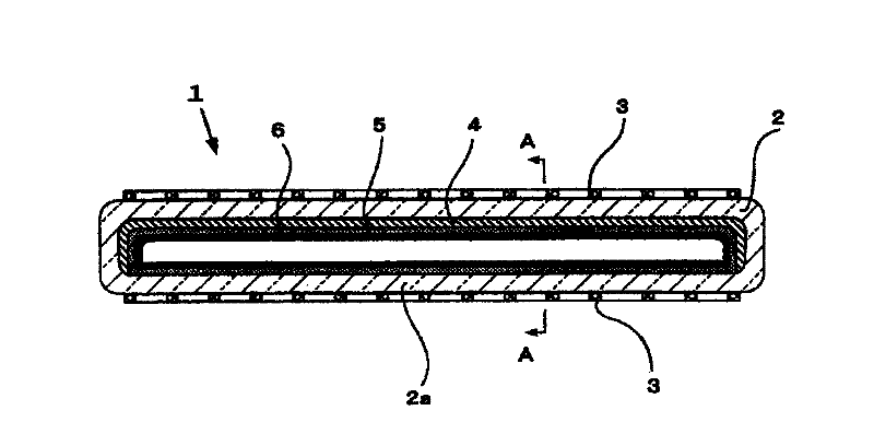
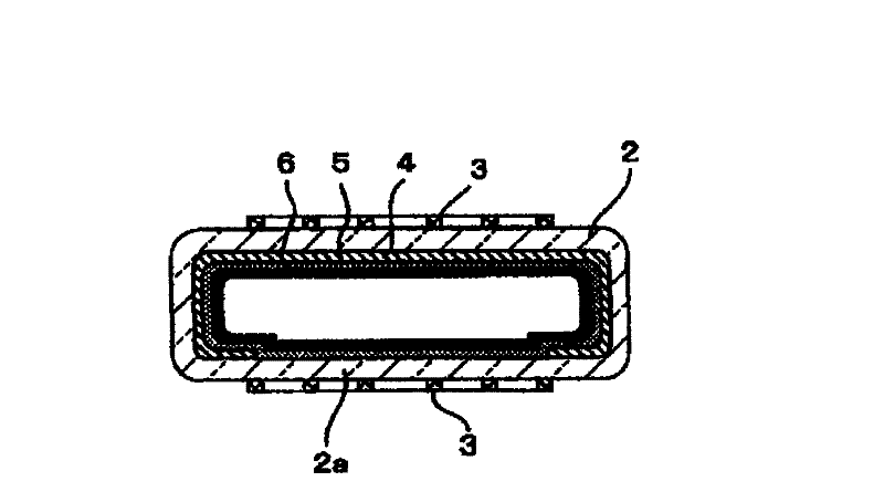
[0018] figure 1 is an axial sectional view of the present invention, figure 2 Is its A-A transverse sectional view.

[0019] exist figure 1 Among them, the phosphor 1 has an arc tube 2 made of quartz glass that is flat as a whole. The size of the luminous tube 2 is, for example, 14mm×42mm×650mm, and the thickness is 2mm.

[0020] A pair of opposite external electrodes 3 and 3 are provided on the upper and lower outer surfaces of the light emitting tube 2 .

[0021] An ultraviolet reflection layer 4 is provided on the inner surface of the arc tube 2 except for the light exit region 2 a where ultraviolet light is taken out from the arc tube 2 . In other words, the ultraviolet reflective layer 4 is formed except for a part of the inner surface of the arc tube 2 along the axial direction, and the region where the ultraviolet reflective layer 4 is not formed constitutes the light emitting region 2 a.

[0022] In addition, inside the ultraviolet reflection layer 4 , a glass la...


PUM


Abstract

The invention provides a fluorescent lamp, which is provided with a light-emitting tube made from quartz glass and emits ultraviolet rays, even if temperature difference between the internal and the external of the lamp is great, a fluorophor layer is not stripped. An ultraviolet reflective layer with silica particles as the main component is formed on a region of the internal surface of the light-emitting tube apart from a light taking-out zone, a glass layer formed by a substance with the softening point lower than that of the quartz glass is formed at the internal side of the ultraviolet reflective layer and the circumference of the light-emitting tube, a fluorophor layer is formed at the internal side of the glass layer, and the thickness of the ultraviolet reflective layer is 30-500 micrometers.

Description

technical field [0001] The present invention relates to a fluorescent lamp, in particular to a fluorescent lamp emitting ultraviolet rays. Background technique [0002] In the manufacturing process of liquid crystal panels used in large-scale televisions, etc., a light source that emits ultraviolet rays with a wavelength of 300 nm to 400 nm as the center is required, and ultraviolet-emitting fluorescent lamps are attracting attention as one of them. [0003] However, so-called hard glasses such as soda glass, borosilicate glass, and aluminosilicate glass are generally used in arc tubes of conventional ultraviolet-emitting fluorescent lamps. Not preferred in lamps. [0004] Therefore, for example, Patent Documents 1, 2, and the like propose fluorescent lamps using quartz glass as an arc tube. This is because quartz glass has good ultraviolet light transmission properties and can efficiently extract light. [0005] However, in the manufacturing process of fluorescent lamps,...

Claims


Application Information

Patent Timeline
Patent Type & Authority Applications(China)
IPC IPC(8): H01J61/35
CPCH01J61/35H01J61/38H01J61/42H01J2261/385
Inventor 松泽聪司竹添法隆
Owner USHIO DENKI KK
Why Eureka
Try Eureka