
Soil turning machine

The technology of a tiller and frame, which is applied in the field of tiller, can solve the problems of shallow plowing of water chestnuts and arrowheads, high labor intensity requirements, and slow labor speed, etc., and achieves a high degree of mechanization and labor-intensive efficiency The effect of low and high work efficiency

Inactive Publication Date: 2014-03-26
黄德胜
View PDF6 Cites 7 Cited by
  • Summary
  • Abstract
  • Description
  • Claims
  • Application Information

AI Technical Summary

Problems solved by technology

[0002] At present, the water chestnut excavator for dry hard field soil uses a plow to turn over the soil. Shallow plows have a lot of damage to water chestnuts and arrowroot skins, are not resistant to storage, and cause a lot of waste. Deep plows are too deep in the next year, so not many people use them. It is still all harvested manually, but the manual speed is slow, the labor intensity is high, and it is time-consuming, the production efficiency is low, and the cost is high. An economical and applicable harvesting machine that can overcome the above-mentioned shortcomings of the prior art is the long-cherished wish of planting users.

Method used


Image

  • Soil turning machine
  • Soil turning machine

Examples


Embodiment 1

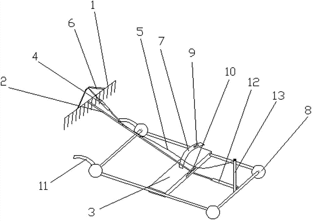
[0022] Embodiment 1: A kind of tiller, the reciprocating mechanism B12 first pushes the sliding frame 3 to move forward, and after moving to a certain distance, the chain cable 5 pulls the rake handle 2 which has been in a horizontal position to set up backward. The coil spring 10 located between the rake handle 2 and the sliding frame 3 produces a certain elastic potential energy. When the reciprocating mechanism B12 drags the sliding frame 3 to move backward, the rake handle 2 will be blocked by the latch 9 at first, Keep the standing state, when the reciprocating mechanism B12 drives the sliding frame 3 to move to a certain position, open the latch 9, and the rake handle 2 will move downward under the action of elastic potential energy and gravity, so that the rake 1 is directly inserted into the soil, and then reciprocates The mechanism continues to move backward, so that the rake handle 2 moves backward. Since the reciprocating mechanism A4 is stretched at this time, the r...

Embodiment 2

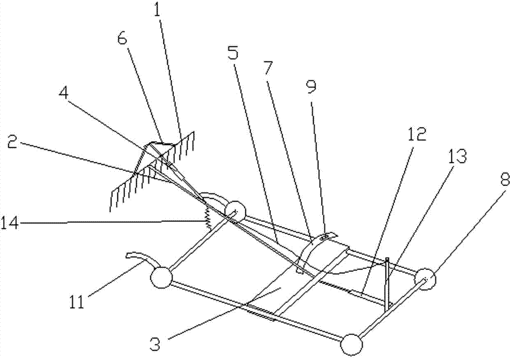
[0023] Embodiment 2: A kind of tiller, the reciprocating mechanism B12 first pushes the sliding frame 3 to move forward, after moving to a certain distance, the chain cable 5 pulls the rake handle 2 which has been in the horizontal position to erect backward, and during the erection process The telescopic spring 14 between the rake handle 2 and the front end of the frame produces a certain elastic potential energy. When the reciprocating mechanism B12 drags the sliding frame 3 to move backward, the rake handle 2 will first be held by the latch 9 to keep In the established state, when the reciprocating mechanism B12 drives the sliding frame 3 to move to a certain position, the latch 9 is opened, and the rake handle 2 will move downward under the action of elastic potential energy and gravity, so that the rake 1 is directly inserted into the soil, and then the reciprocating mechanism Continue to move backward, so that the rake handle 2 moves backward. Since the reciprocating mech...


PUM


Abstract

The invention relates to a soil turning machine. The soil turning machine comprises a rake, a rake handle and a prying rod, which are arranged on a rack, wherein the prying rod is downwards connected with the rack, the rear end of the prying rod is connected with a reciprocating mechanism A, and the other end of the reciprocating mechanism A is connected with the rake handle connected to the rear end of the rake, so that the rake, the prying rod and the reciprocating mechanism A form a triangular soil turning structure; the rake handle is connected to the rear end of the prying rod, and is movably connected to a sliding frame through a coil spring or is connected to the rack or another part on the rack through a retractable spring; a support structure capable of supporting the rake handle is arranged on the sliding frame; the sliding frame is also connected with a reciprocating mechanism B; the other end of the reciprocating mechanism B is connected with a bracket; a chain cable is also arranged on the rake handle; the other end of the chain cable is connected with the bracket arranged at the tail end of the rack. The soil turning machine has the characteristics of convenience in use, simple structure, high mechanization degree, reduction in labor cost and high working efficiency, water chestnuts, arrowheads and the like can be collected in cold winter, and the probable problems of manual collection are solved.

Description

technical field [0001] The invention relates to the field of agricultural machinery, in particular to a soil tiller for excavating crops such as horseshoes and arrowroot buried underground. Background technique [0002] At present, the water chestnut excavator for dry hard field soil uses a plow to turn over the soil. Shallow plows have a lot of damage to water chestnuts and arrowroot skins, are not resistant to storage, and cause a lot of waste. Deep plows are too deep in the next year, so not many people use them. It is still all harvested manually, but the labor speed is slow, the labor intensity is high, and it is time-consuming, the production efficiency is low, and the cost is high. An economical and applicable harvesting machine that can overcome the above-mentioned shortcomings of the prior art is the long-cherished wish of planting users. Contents of the invention [0003] It is a soil tiller suitable for picking underground crops, which is suitable for dry mud fi...

Claims


Application Information

Patent Timeline
Patent Type & Authority Applications(China)
IPC IPC(8): A01D13/00
Inventor 黄德胜
Owner 黄德胜
Learn More