
Pulse condition tester

A pulse condition and detector technology, applied in the direction of the catheter, etc., can solve the problems of inability to adjust the distance, complex structure, large volume, etc., and achieve the effect of convenient maintenance and assembly, simple structure, and low cost

Active Publication Date: 2014-03-26
SHENZHEN INST OF ADVANCED TECH
View PDF5 Cites 18 Cited by
  • Summary
  • Abstract
  • Description
  • Claims
  • Application Information

AI Technical Summary

Problems solved by technology

Its disadvantage is that the obtained pulse signal is not stable enough, and it is easy to interfere with each other. The distance between each probe is fixed, and it cannot be adjusted according to the distance between the wrist, guan, and ruler, and it is not universal for the measurement population.
In addition, some pulse detectors use complex mechanical transmission mechanisms to simulate the three-part pulse-taking method of traditional Chinese medicine.
As a result, its structure is complex, bulky, not easy to carry, not suitable for family or community use

Method used


Image

  • Pulse condition tester
  • Pulse condition tester
  • Pulse condition tester

Examples


Embodiment Construction

[0022] The following will clearly and completely describe the technical solutions in the embodiments of the present invention with reference to the accompanying drawings in the embodiments of the present invention. Obviously, the described embodiments are only some, not all, embodiments of the present invention. Based on the embodiments of the present invention, all other embodiments obtained by persons of ordinary skill in the art without creative efforts fall within the protection scope of the present invention.

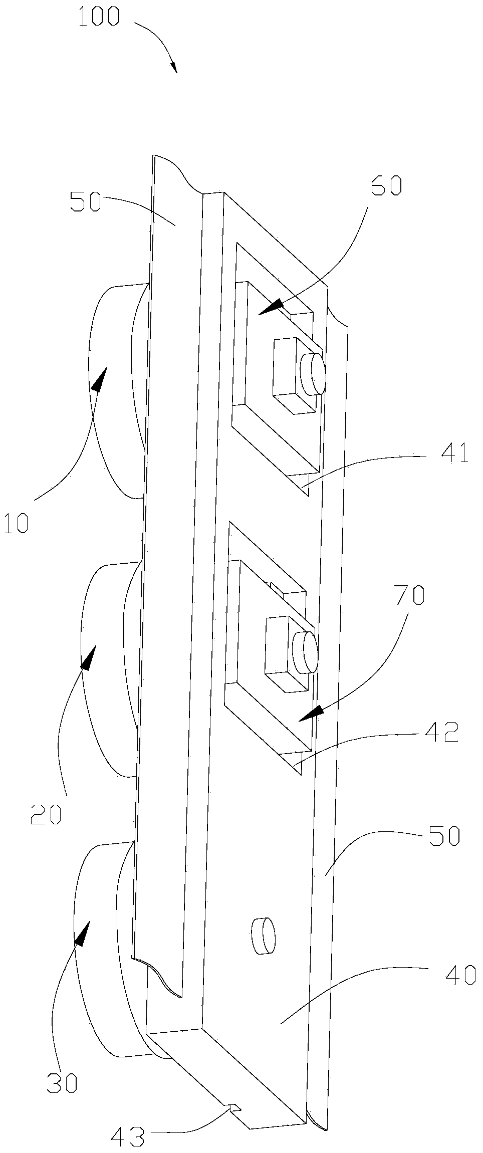
[0023] Embodiments of the present invention will be described below with reference to the accompanying drawings. see figure 1 , is a schematic structural diagram of the pulse condition detector 100 provided by the embodiment of the present invention. The pulse condition detector 100 adopts technologies such as biosensing technology, machinery, and human mechanics to realize the floating and sinking of the pulse condition information of the three parts of the wrist...


PUM


Abstract

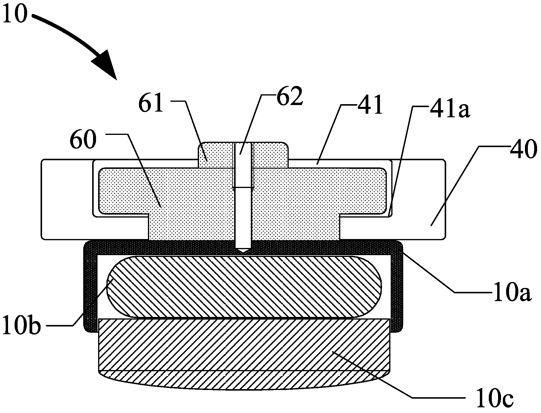
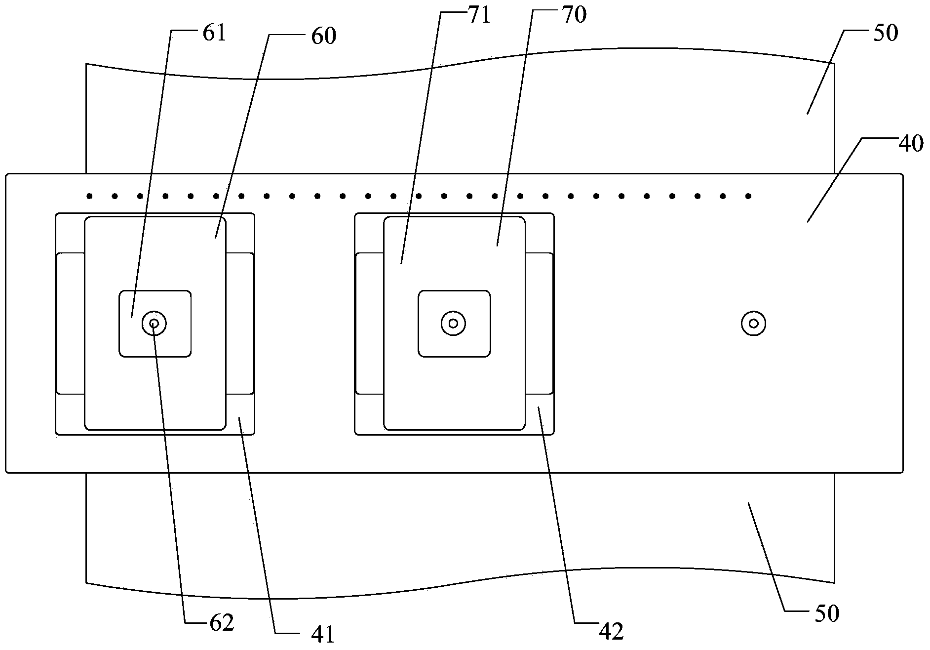
The invention discloses a pulse condition tester. The pulse condition tester comprises a first probe, a second probe, a third probe and a support. The first probe, the second probe and the third probe are sequentially arranged in parallel, are the same in structure, and all comprise casing pipes, air bags and sensors. The air bags and the sensors are all matched and accommodated in the casing pipes, and the air bags are clamped between the casing pipes and the sensors and used for conducting inflation and deflation to drive the sensors to slide in the casing pipes. A first sliding chute and a second sliding chute are formed in the surface of the support in a penetrating mode, the first probe is connected into the first sliding chute in a sliding mode, the second probe is connected into the second sliding chute in a sliding mode, and the third probe is fixedly connected to the support. According to the pulse condition tester, the first probe and the second probe can be manually adjusted, and the pulse condition tester can more easily align with inch, bar and cubit acupuncture points. The pulse condition tester is simple in structure, convenient to operate, maintain and assemble, small in size, easy to wear, low in cost, and high in universality, and pulses can be taken for multiple crowds.

Description

technical field [0001] The invention relates to the field of medical equipment, in particular to a pulse condition tester. Background technique [0002] The human pulse system is not only an important way for the human body to transport nutrients, transfer energy and disseminate various physiological and pathological information, but also an important part of the cardiovascular system. Therefore, the pulse is considered to be the symphony of life activities of the human body. Chinese medicine can diagnose diseases and the activity rules of viscera by observing and analyzing the characteristics of the pulse condition of the human body—that is, pulse diagnosis, commonly known as "pulse number". [0003] In Chinese medicine, the Cunkou three-part nine-waiting pulse method is that the doctor can know the pathological changes of the human body's internal organs by touching the Cun, Guan and Chi parts of the patient's radial artery with his fingers and pressing the "sinking, middl...

Claims


Application Information

Patent Timeline
Patent Type & Authority Applications(China)
IPC IPC(8): A61B5/02
Inventor 金雷姜永涛刘文权于文龙冯广智陈毅崔晗
Owner SHENZHEN INST OF ADVANCED TECH
Learn More