Low-temperature plasma treating system

A low-temperature plasma and treatment system technology, applied in the field of ion treatment systems, can solve the problems of inconvenient operation, increase the labor intensity of doctors, etc., and achieve the effects of safe and reliable use and improved treatment efficiency.

Inactive Publication Date: 2014-03-26
上海方润医疗科技股份有限公司
View PDF8 Cites 10 Cited by
  • Summary
  • Abstract
  • Description
  • Claims
  • Application Information

AI Technical Summary

Problems solved by technology

[0011] However, in the existing low-temperature plasma equipment, the switching of the output energy and the energy output mainly rely on the foot switch and the operation buttons on the main panel of the low-temperature plasma equipment. The doctor must step on the foot when using the electrode device to treat the patient. Step on the switch; when switching the gear of the treatment energy, the display panel of the host must be observed at the same time, which causes inconvenience in operation and increases the labor intensity of the doctor

Method used


Image

  • Low-temperature plasma treating system
  • Low-temperature plasma treating system
  • Low-temperature plasma treating system

Examples


Embodiment 1

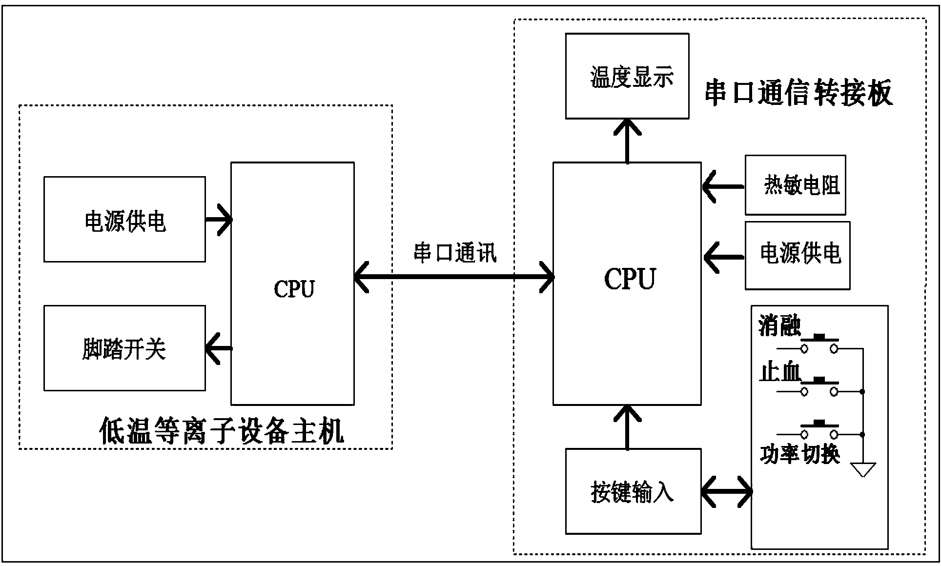
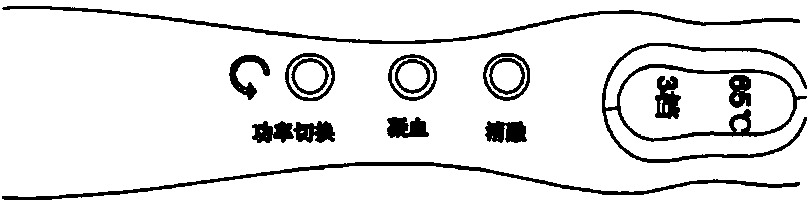
[0037]This embodiment provides a low-temperature plasma treatment system, including a treatment head and a host, the treatment head includes an electrode head, an insulating tube, a handle, a wire and a connector, wherein the first end of the insulating tube is connected to the electrode head , the second end of the insulating tube is connected to the first end of the handle; the electrode head is connected to the host through a wire and a connector, the electrode head is provided with a thermistor; the handle is provided with a button A switch and a display module, the handle is provided with a serial port communication adapter board, the serial port communication adapter board includes a main control module, a power supply, a key input module and a serial port communication module, and the key input module reads the key switch State information, the thermistor reads the temperature information of the electrode head, the thermistor, key input module, and display module communi...

Embodiment 2

[0047] The structure of this embodiment is basically the same as that of Embodiment 1, the difference is that in this embodiment, the treatment head also includes a drip line and a suction line, and the drip line communicates with the insulating tube to form the first part of the liquid circulation. A channel is used for dripping liquid into the body; the electrode head has a through hole, and the suction pipeline communicates with the through hole of the electrode head to form a second channel for liquid circulation and is used for sucking liquid from the body. A flow control valve may also be arranged on the suction pipeline and the infusion pipeline for controlling the flow of suction or infusion fluid.

Embodiment 3

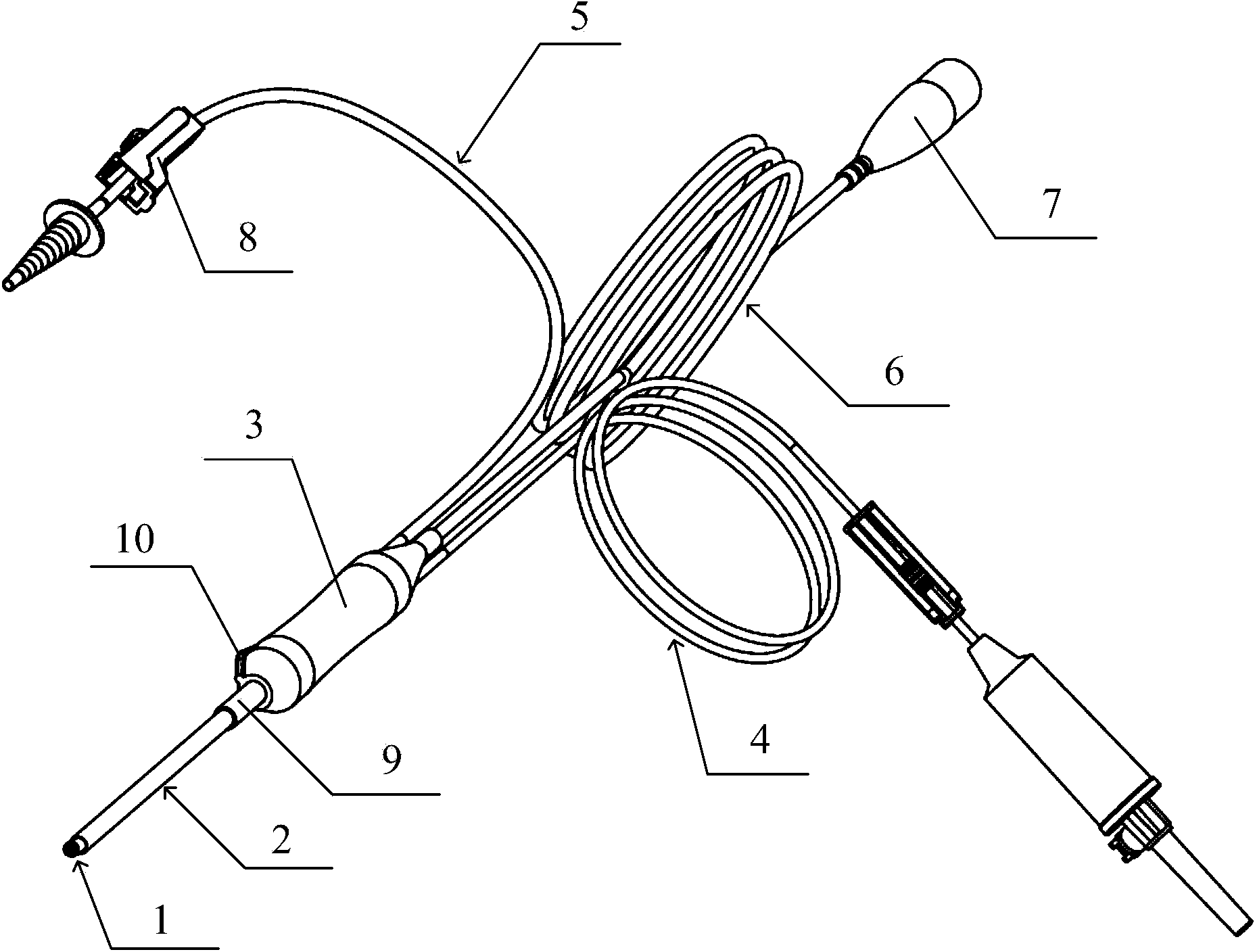
[0049] Such as image 3 As shown, the structures of this embodiment and Embodiment 2 are basically the same, the difference is that, in this embodiment, the outer surface of the first end of the handle 3 is further provided with a protrusion 10 . When the user is holding the handle 3 to push the electrode device, especially when holding the handle 3 to push the electrode head 1 into the organ tissue, the protrusion has the function of anti-slip, which increases the resistance of the hand and prevents the electrode from being pushed. The slipping during the entry process is convenient for the doctor's operation.

[0050] The treatment head also includes a fixed sleeve 9, the inner diameter of the fixed sleeve 9 is set to cooperate with the outer diameter of the second end of the insulating tube 2, the inside of the fixed sleeve 9 is provided with a support bracket, and the second end of the insulating tube 2 It is inserted into the fixed sleeve 9 and fixedly connected with the...


PUM


Abstract

The invention provides a low-temperature plasma treating system. The function of controlling melting, coagulation and energy switching of a low-temperature plasma device is transplanted to a handle of the treating system in a mode of key switches. A display module is assembled on the electrode handle portion and displays the current power level and the real-time temperature of an electrode head. The key switches and the display module are connected with a low-temperature plasma treating instrument main machine in a serial port communication mode through a connecting cable of the electrode head. According to the low-temperature plasma treating system, treatment can be conducted as long as a user presses down the key switches on the handle, and then energy output and switching of radio frequency energy can be achieved; in addition, the user can observe the current energy level and the electrode temperature through display in real time, using is safe and reliable, the treatment efficiency is improved, the structure is simple, and the labor intensity of the doctor is relieved.

Description

technical field [0001] The invention relates to the technical field of medical devices, in particular to a low-temperature plasma treatment system. Background technique [0002] Human beings' systemic understanding of plasma began with the study of gas discharge in the 1930s, and the concept of plasma was established in the early 20th century, that is, a system with macroscopic spatiotemporal inertness composed of a large number of specifically interacting charged particles. Plasma can be divided into high-temperature plasma and low-temperature plasma according to the relative temperature of charged particles. [0003] Plasma radiofrequency ablation was first applied in 1995. In 1995, the first company was successfully registered and used in the US FDA. It has been widely used in the medical industry in 1997. The radiofrequency ablation treatment technology in my country started almost at the same time as the international upsurge. The introduction of A variety of radio freq...

Claims


Application Information

Patent Timeline
Patent Type & Authority Applications(China)
IPC IPC(8): A61B18/04
Inventor 王远强秦杰孔凡斌
Owner 上海方润医疗科技股份有限公司
Why Eureka
Try Eureka