

Spin welding device
A technology of spin welding and welding seam, applied in the field of machinery, can solve the problems of heavy workload, low welding quality, uneven welding points, etc., to achieve the effect of stable welding quality and efficient production
Inactive Publication Date: 2014-03-26
重庆针尖内燃机部件制造有限公司
View PDF0 Cites 8 Cited by
- Summary
- Abstract
- Description
- Claims
- Application Information
AI Technical Summary
Problems solved by technology
[0002] Most of the current welding devices use manual welding or semi-mechanical mechanical rotary manual welding. The welding points are uneven, the surface is not smooth, the welding quality is not high, and the workload is relatively large.
Method used
View moreImage
Smart ImageViewing Examples

Examples
Embodiment Construction
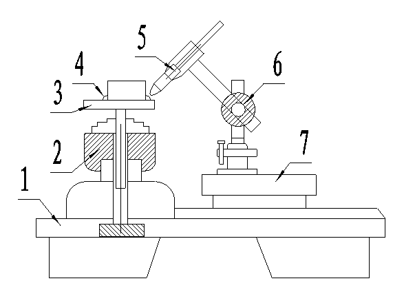
[0009] Below in conjunction with Fig. 1, the specific working conditions proposed by the present invention are described in detail. The slow-speed variable frequency motor 2 drives the welding seam 4 of the welding part 3 to rotate at a constant speed. There is a stable welding working distance between seams 4, so as to realize continuous automatic welding of welding parts and special-shaped welding seams 4, obtain stable welding quality more effectively, and realize its high-efficiency production.
Login to View More PUM
 Abstract
The invention relates to a spin welding device. A low-speed variable-frequency motor and a movable platform are arranged on a working table, a welding part and a welded joint are fixed to the low-speed variable-frequency motor, a welding gun and a welding gun lifting motor are fixed to a movable platform, and the welded joint on the welding part is driven to rotate at a constant speed through the low-speed variable-frequency motor; meanwhile, the welding gun is controlled through the welding gun lifting motor and the movable platform, a stable welding work distance is kept between the welding gun and the welded joint all the time, and therefore continuous automatic welding of the welding part and the special-shaped welded joint is achieved, stable welding quality is more efficiently achieved, and the efficient production of the spin welding device is achieved.
Description
technical field [0001] The invention is a rotary welding device, which belongs to the technical field of machinery. Background technique [0002] Most of the current welding devices use manual welding or semi-mechanical mechanical rotation manual welding. The welding points are uneven, the surface is not smooth, the welding quality is not high, and the workload is relatively large. Contents of the invention [0003] The purpose of the present invention is to provide a rotary welding device, through the uniform rotation of the slow frequency conversion motor on the workbench, the welding torch can automatically weld parts, realize uniform, smooth and beautiful welding points, stabilize the welding quality, and improve work efficiency the goal of. [0004] Its purpose is achieved in this way, a rotary welding device is composed of a workbench, a slow frequency conversion motor, welding parts, welding seams, a welding torch, a welding torch lifting motor, and a mobile platfo...
Claims
Login to View More Application Information
Patent Timeline
 Patent Type & AuthorityApplications(China)
IPC IPC(8): B23K37/00B23K37/02
CPCB23K37/0252B23K37/0461B23K37/047Y02P70/10
Inventor舒航
Owner重庆针尖内燃机部件制造有限公司