
Feeding and discharging device for centerless grinding machine for performing plunge-cut grinding on bearing rollers

A technology of cutting into grinding and bearing rollers, which is applied in the direction of grinding machines, grinding feed movement, grinding/polishing equipment, etc., and can solve problems such as slow loading and unloading speed, inability to completely remove scratches from rollers, and appearance quality problems , to avoid bruising, simple structure and reasonable design

Active Publication Date: 2014-03-26
无锡市明鑫机床有限公司
View PDF5 Cites 9 Cited by
  • Summary
  • Abstract
  • Description
  • Claims
  • Application Information

AI Technical Summary

Problems solved by technology

[0002] At present, in China, the outer circle of bearing rollers of medium specifications (hereinafter referred to as rollers) is ground by the cutting method, which is generally processed by high-precision centerless grinders or bearing grinders. Among them, bearing grinders have mature loading and unloading, but high-precision centerless grinders The roller loading and unloading of processing in the cut-in method is only the loading and unloading of the push-pull structure. Although this loading and unloading method is low in cost and simple in structure, the loading and unloading speed is slow. Depending on the slight scratches produced when sliding on the guide wheel, this kind of scratches is a serious appearance quality problem for high-precision rollers, so this kind of scratches must be removed by super-finishing or polishing, but even so, there are still a few Roller cannot fully remove scratches

Method used


Image

  • Feeding and discharging device for centerless grinding machine for performing plunge-cut grinding on bearing rollers
  • Feeding and discharging device for centerless grinding machine for performing plunge-cut grinding on bearing rollers

Examples


Embodiment Construction

[0010] The present invention will be further described below in conjunction with specific drawings and embodiments.

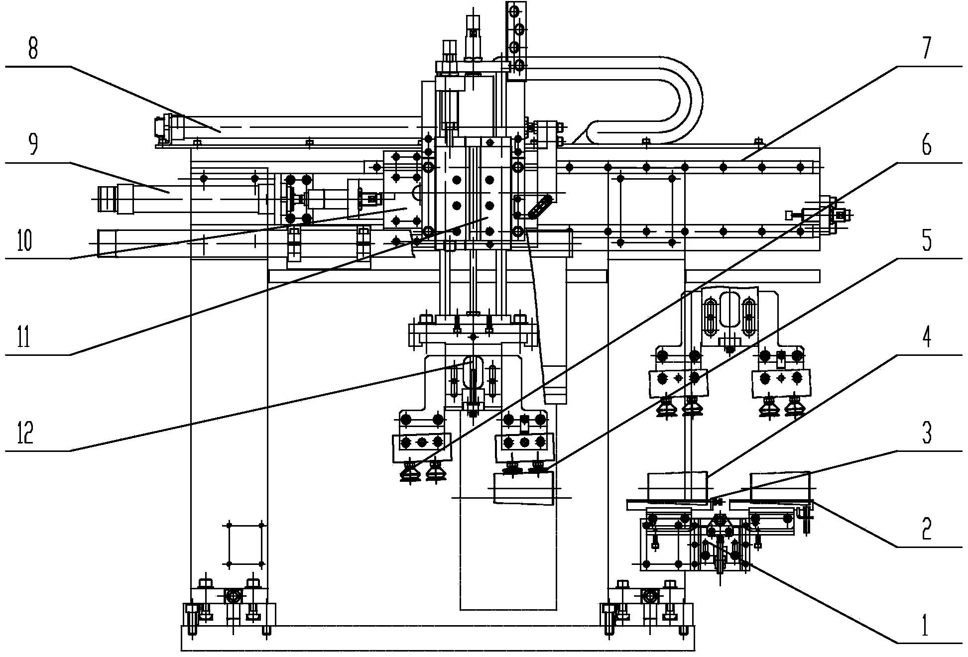
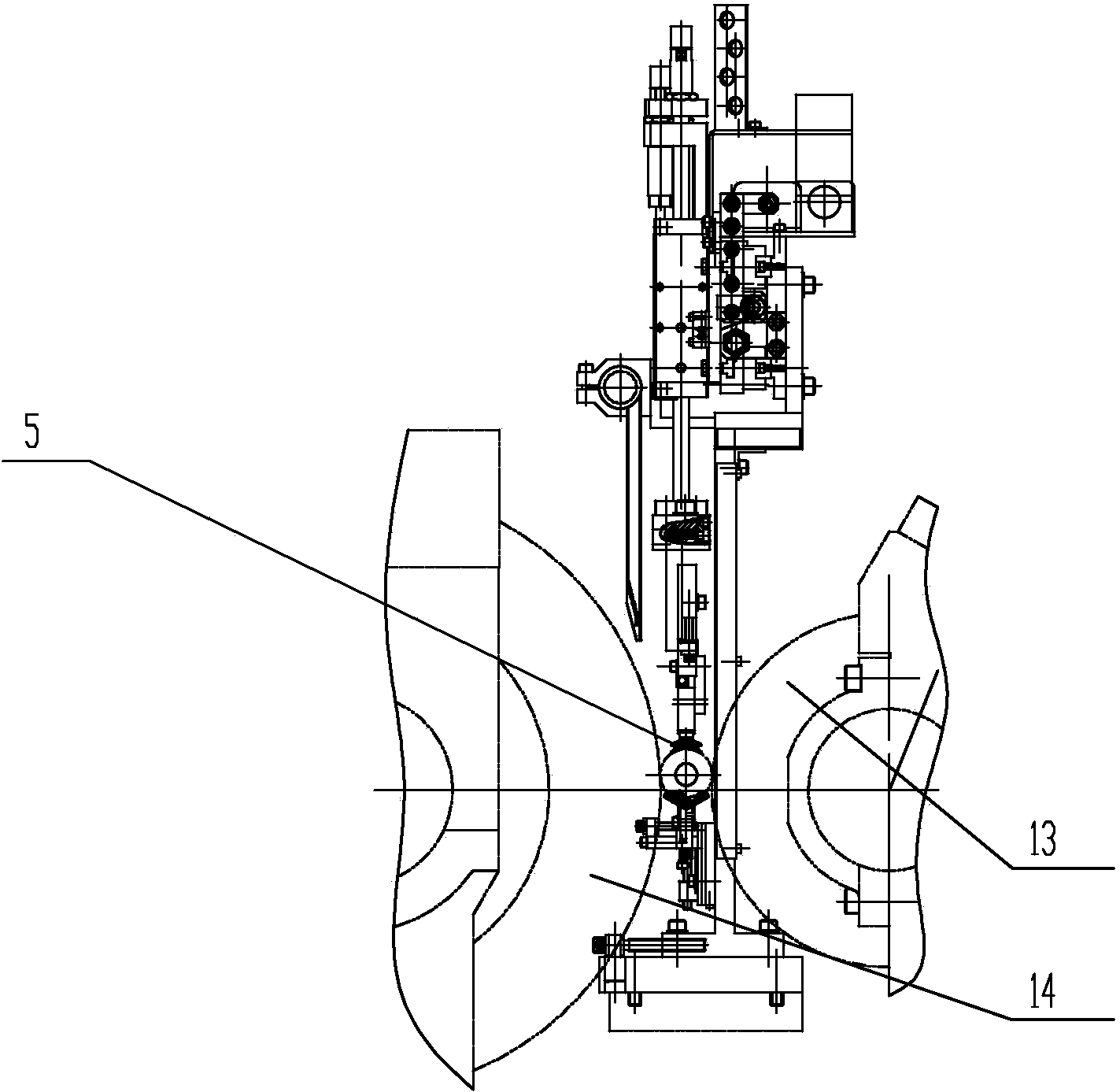
[0011] Such as figure 1 , figure 2 As shown, it includes material rack 1, blanking V-shaped groove 2, loading V-shaped groove 3, tapered roller 4, blanking suction cup 5, loading suction cup 6, guide rail 7, first cylinder 8, second cylinder 9, Skateboard 10, guide cylinder 11, mechanical arm 12, guide wheel 13, grinding wheel 14 etc.

[0012] Such as figure 1 , figure 2 As shown, a centerless grinding machine of the present invention cuts into the grinding bearing roller loading and unloading device, including a grinding frame. Move left and right; the first cylinder 8 for controlling the left and right movement of the slide plate 10 is arranged on the top of the grinding frame, specifically, the piston rod of the first cylinder 8 is connected to the slide plate 10, so that the first cylinder 8 and the slide plate 10 can be realized. There is also a gui...


PUM


Abstract

The invention belongs to the technical field of machining equipment, and relates to a centerless grinding machine, in particular to a feeding and discharging device for a centerless grinding machine for performing plunge-cut grinding on bearing rollers. The feeding and discharging device comprises a grinding frame, wherein a transverse guide track is fixed on the upper portion of the grinding frame; a sliding plate is slidably arranged on the guide track; a first cylinder is arranged on the top of the grinding frame; a piston rod of the first cylinder is connected to the sliding plate; a guiding cylinder is arranged on the sliding plate; a piston rod of the guiding cylinder faces the vertical direction; the lower end of the piston rod of the guiding cylinder is fixedly connected with a mechanical arm; the mechanical arm is provided with two support arms; and a discharging sucker and a feeding sucker are respectively arranged on mounting workstations of the two support arms.

Description

technical field [0001] The invention belongs to the technical field of machining equipment, and relates to a centerless grinder, in particular to a loading and unloading device for a centerless grinder which cuts into and grinds bearing rollers. Background technique [0002] At present, in China, the outer circle of bearing rollers of medium specifications (hereinafter referred to as rollers) is ground by cutting in, and it is generally processed by high-precision centerless grinders or bearing grinders. Among them, bearing grinders have mature loading and unloading, but high-precision centerless grinders The roller loading and unloading of processing in the cut-in method is only the loading and unloading of the push-pull structure. Although this loading and unloading method is low in cost and simple in structure, the loading and unloading speed is slow. Depending on the slight scratches produced when sliding on the guide wheel, this kind of scratches is a serious appearance...

Claims


Application Information

Patent Timeline
Patent Type & Authority Applications(China)
IPC IPC(8): B24B5/35
CPCB24B5/35B24B5/355B24B41/005
Inventor 邓明周振民
Owner 无锡市明鑫机床有限公司
Learn More