Supercharge Your Innovation With Domain-Expert AI Agents!

Semi-rigid solar battery wing of spacecraft

A technology for space vehicles and solar cells, which is applied to the power supply system of aerospace vehicles, etc., can solve the problems of circuit short-circuit failure mode, low power generation efficiency, unsuitable space use, etc., to achieve good atomic oxygen resistance, high bearing capacity, and power generation. high power effect

Inactive Publication Date: 2014-03-26
SHANGHAI AEROSPACE SYST ENG INST
View PDF7 Cites 18 Cited by
  • Summary
  • Abstract
  • Description
  • Claims
  • Application Information

AI Technical Summary

Problems solved by technology

[0002] At present, the solar cell wings used in the space orbit environment in our country are all rigid solar cell wings. Due to the complex space environment of aircraft flight, the traditional rigid solar cell wings are gradually unsuitable as solar cell wings for space vehicles.
[0003] For example, there is strong atomic oxygen erosion in the low-orbit environment, which is easy to cause erosion effect on the surface of Kapton film, the carrier of the battery module mounted on the traditional rigid substrate, resulting in the failure mode of short circuit in the circuit, which directly affects the success or failure of the flight mission.
The on-orbit working conditions of the aircraft are complex, requiring multiple orbit changes, maintenance, and no less than 6 rendezvous, docking, and separation, etc. Rigid solar cell wings are difficult to meet the use requirements
[0004] In addition, the power generation efficiency of the solar panel is directly related to the temperature environment. The photoelectric conversion efficiency of the battery module is low at high temperature, and the power generation efficiency of the aluminum honeycomb plus carbon fiber grid panel of the rigid solar cell wing is low, which is not suitable for space use.

Method used


Image

  • Semi-rigid solar battery wing of spacecraft
  • Semi-rigid solar battery wing of spacecraft
  • Semi-rigid solar battery wing of spacecraft

Examples


Embodiment Construction

[0024] At present, the solar cell wings used in the space orbit environment in our country are all rigid solar cell wings. Due to the complex space environment of aircraft flight, the traditional rigid solar cell wings are gradually unsuitable as solar cell wings for space vehicles.

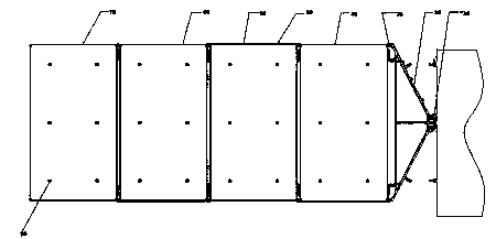
[0025] In view of the foregoing, the technical solution of the present invention provides a semi-rigid solar battery wing of a space vehicle, such as figure 1 The semi-rigid solar cell wing shown comprises:

[0026] A root deployment locking mechanism 19 connected to the spacecraft;

[0027] Inter-panel deployment locking mechanism 20;

[0028] A connecting frame 30 connecting the root deployment locking mechanism 19 and the inter-board deployment locking mechanism 20;

[0029] The inner semi-rigid battery board 40 , the middle inner semi-rigid battery board 50 , the middle and outer semi-rigid battery board 60 and the outer semi-rigid battery board 70 which are connected in sequence;

[0030]...


PUM


Abstract

A semi-rigid solar battery wing of a spacecraft comprises a root unfolding locking mechanism, an interpolate unfolding locking mechanism, a connection frame, an inner semi-rigid battery plate, a middle inner semi-rigid battery plate, a middle outer semi-rigid battery plate, an outer semi-rigid battery plate, an unfolding synchronization device and a compressing release mechanism, wherein the root unfolding locking mechanism is connected with the spacecraft, the connection frame is connected with the root unfolding locking mechanism and the interpolate unfolding locking mechanism, the inner semi-rigid battery plate, the middle inner semi-rigid battery plate, the middle outer semi-rigid battery plate and the outer semi-rigid battery plate are movably connected sequentially, the inner semi-rigid battery plate is connected with the connection frame through the interpolate unfolding locking mechanism, the unfolding synchronization device is arranged on the middle inner semi-rigid battery plate, and the compressing release mechanism is arranged on the outer semi-rigid battery plate. By means of the technical scheme, a short circuit is avoided, and electricity generation efficiency of the solar battery wing is improved.

Description

technical field [0001] The invention relates to aerospace vehicle equipment, in particular to a semi-rigid solar cell wing of a space vehicle. Background technique [0002] At present, the solar cell wings used in the space orbit environment in our country are all rigid solar cell wings. Due to the complex space environment of aircraft flight, the traditional rigid solar cell wings are gradually unsuitable as solar cell wings for space vehicles. [0003] For example, there is strong atomic oxygen erosion in the low-orbit environment, which is easy to cause erosion effect on the surface of the Kapton film carrier of the traditional rigid substrate mounting battery module, resulting in a failure mode of short circuit in the circuit, which directly affects the success or failure of the flight mission. The in-orbit working conditions of the aircraft are complex, requiring multiple orbit changes, maintenance, and no less than 6 rendezvous, docking and separation, etc. Rigid solar...

Claims


Application Information

Patent Timeline
IPC IPC(8): B64G1/44
Inventor 王治易张玉花董毅杨华星陈建祥顾珏华
Owner SHANGHAI AEROSPACE SYST ENG INST
Features
  • R&D
  • Intellectual Property
  • Life Sciences
  • Materials
  • Tech Scout
  • Unparalleled Data Quality
  • Higher Quality Content
  • 60% Fewer Hallucinations
Learn More