Crank slow-down swinging feeding mechanism

A technology of feeding mechanism and crank, applied in the field of decelerating swing feeding mechanism

Inactive Publication Date: 2014-03-26
CHONGQING CHENGSHUO TECH
View PDF0 Cites 18 Cited by
  • Summary
  • Abstract
  • Description
  • Claims
  • Application Information

AI Technical Summary

Problems solved by technology

When the user needs to convert the linear motion of the cylinder into reciprocating swing, it needs to be driven by the mechanical structure, and the motion mode of the moving parts must be changed, which undoubtedly poses a problem for the designer.

Method used


Image

  • Crank slow-down swinging feeding mechanism

Examples


Embodiment Construction

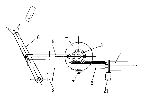
[0012] Such as figure 1 As shown, the crank deceleration swing feeding mechanism of the present invention includes a vertically placed bracket, and the bracket is provided with a cylinder 1, the piston rod of the cylinder 1 is fixedly connected to a rack 2, and the tooth surface of the rack 2 faces upward and engages There is a gear 3, a crank disc 4 is connected with a coaxial key on the gear 3, and a connecting rod 5 is hinged eccentrically on the crank disc 4, and the free end of the connecting rod 5 is hinged at the middle part of the rocker arm 6, The fixed end of the rocker arm 6 is hinged on the support. The above-mentioned cylinder 1, rack 2, gear 3, crank disc 4, connecting rod 5 and swing arm 6 are placed on the same side of the bracket, and the back of the rack 2 on the bracket is located directly below the gear and there is a pressing tooth Strip guide roller 7. There are also two blocks 21 that block the movement of the rack 2 on the support. A pressure sensor ...


PUM


Abstract

The invention discloses a crank slow-down swinging feeding mechanism comprising a support. An air cylinder is fixed on the support, a piston rod of the air cylinder is fixedly connected with a toothed bar with a tooth surface facing upwards, the tooth surface is meshed with a gear, a crank disc is coaxially arranged on the gear, the crank disc is eccentrically provided with a connecting rod in a hinged manner, the free end of the connecting rod is hinged to the middle of a rocker arm with the fixed end hinged to the support, and the feeding end of the rocker arm is provided with a workpiece clamping groove. Since the piston rod of the air cylinder is linked with the crank disc, linear motion of the air cylinder can be converted into circular motion of the crank disc through the toothed bar and the toothed gear, and manufacturing cost is greatly saved. In addition, according to the characteristics of the structure, motion speed of the rocker arm at biggest swinging positions on both sides is low, workpiece feeding and discharging at the biggest swinging positions on both sides of the rocker arm can be more accurate, and the workpiece can be prevented from flying out of the clamping groove due to excessively high rotation speed of the rocker arm.

Description

technical field [0001] The invention relates to a workpiece feeding device, in particular to a decelerating swing feeding mechanism utilizing a crank. Background technique [0002] In the mechanical structure, many power devices are linear reciprocating power devices, such as cylinders. When the user needs to convert the linear motion of the cylinder into reciprocating swing, it needs to be transmitted through the mechanical structure, and the motion mode of the moving parts must be changed, which undoubtedly poses a problem for the designer. Contents of the invention [0003] The purpose of the present invention is to provide a crank deceleration oscillating feeding mechanism, which has a simple structure and can convert linear motion into reciprocating oscillating to realize feeding of workpieces. [0004] In order to achieve the above object, the technical solution of the present invention is: the crank deceleration swing feeding mechanism includes a bracket, the brack...

Claims


Application Information

Patent Timeline
Patent Type & Authority Applications(China)
IPC IPC(8): B65G47/82
Inventor 李清芬
Owner CHONGQING CHENGSHUO TECH
Why Eureka
Try Eureka