Automatic cover pressing machine

A capping machine, automatic technology, applied to bottle/container caps, capping containers with caps, bottle filling, etc., can solve problems such as prolonging capping time, reducing production efficiency, and inflating barrel caps, so as to improve pressure The effect of improving installation efficiency, reducing operating costs, and facilitating overlapping

Inactive Publication Date: 2014-03-26
天津滨海新区大港圣益油脂有限公司
View PDF0 Cites 3 Cited by
  • Summary
  • Abstract
  • Description
  • Claims
  • Application Information

AI Technical Summary

Problems solved by technology

[0003] This kind of capping machine has the following disadvantages: 1. During the capping process, the gas in the barrel is not easy to be removed, and the upper part of the barrel lid is easy to cause gas blowing, which cannot be stacked or transported, and will eventually occupy a lot of space, increasing the working area and site costs; 2. .The power of the machine is not easy to control. When it is too large, it is easy to crush the barrel body, so the capping time is prolonged and the production efficiency is reduced; 3. The capping is often done manually, and the worker operates the capping machine. One operation is completed One-time capping operation; although automatic capping can also be realized through circuit control to save manpower, the control system is complicated and the cost is high

Method used


Image

  • Automatic cover pressing machine

Examples


Embodiment Construction

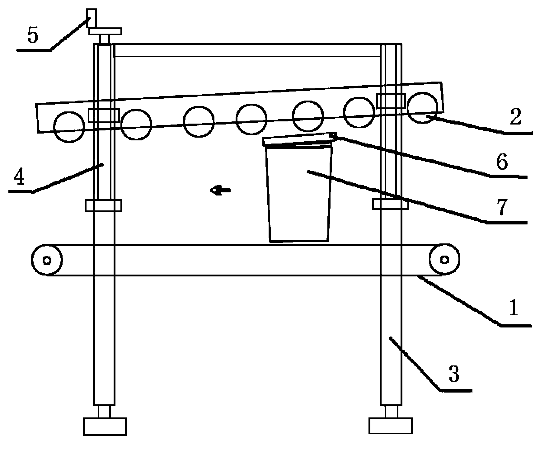
[0011] When the number of rollers N=8 and the guide angle θ=10° in conjunction with the accompanying drawings, the present invention will be further described.

[0012] Such as figure 1 As shown, the conveyor belt 1 that conveys the barrel body 7 and the roller 2 that squeezes the barrel lid 6 when the barrel body 7 and the barrel lid 6 pass through the bracket 3 above the conveyor belt 1, the roller 2 is installed on the bracket 3, and the bracket 3 straddles On the conveyor belt 1, the conveyor belt 1 is driven by a motor, and the output shaft of the motor is connected with the driving wheel through a reducer, and then the driving wheel drives the driven wheel to rotate, thereby making the conveyor belt rotate. All the rollers 2 share two pairs of brackets 3 and are arranged in a row to form a roller board. There is a guide angle θ between the conveyor belt 1 and the roller boards to allow the bucket body 7 to pass through. The brackets 3 have a lifting adjustment mechanism....


PUM


Abstract

The invention provides an automatic cover pressing machine. According to the automatic cover pressing machine, a barrel cover does not blow up, the press-fitting efficiency is high and cost is low. The automatic cover pressing machine comprises a conveying belt for conveying a barrel and a roller which is located above the conveying belt and is used for squeezing the barrel cover when the barrel and the barrel cover pass through a support, wherein the roller is installed on the support, the support is arranged on the conveying belt in a cross-over mode, and the conveying belt is driven by a motor. Due to the fact that a guide included angle theta which is larger than or equal to 7 degrees and smaller than or equal to 15 degrees and allows the barrel to pass through is formed between the conveying belt and a roller plate, the roller rolls on the barrel cover during press-fitting, air is gradually exhausted in the process, and accordingly the barrel cover does not blow up, and stacking is facilitated when the barrels are stacked and transported. Pressure on the barrel gradually increases, and the barrel is protected against being damaged in the squeezing process in the largest degree under the same condition. The automatic cover pressing machine is simple in structure and ingenious in concept; when the automatic cover pressing machine operates, what is needed is to rotate the conveying belt, the roller can press the cover without power, and accordingly operation cost is reduced.

Description

technical field [0001] The invention relates to the field of capping machinery, in particular to an automatic capping machine. Background technique [0002] Plastic drums have long been used as packaging containers for sales terminals such as lubricants, paints, and coatings. During production, first put a certain amount of lubricating oil, paint, etc. into a plastic bucket, then put the lid on the bucket, and finally press down the lid hard, using the elasticity of the plastic, the barb on the bucket is hooked on the bucket The cap is fitted with corresponding barbs to form an interlock, thereby completing the encapsulation process of lubricants, paints, etc. In the prior art, the capping machines are all pneumatic or hydraulic devices, which press-fit the bung vertically from top to bottom. [0003] This kind of capping machine has the following disadvantages: 1. During the capping process, the gas in the barrel is not easy to be removed, and the upper part of the barrel...

Claims


Application Information

Patent Timeline
Patent Type & Authority Applications(China)
IPC IPC(8): B67B3/00
Inventor 韩忠义
Owner 天津滨海新区大港圣益油脂有限公司
Why Eureka
Try Eureka