Sludge dewatering machine capable of lowering sludge water content

A sludge dewatering machine and water content technology, applied in the direction of dewatering/drying/concentrating sludge treatment, etc., can solve the problems that the equipment cannot achieve the expected treatment effect, the spiral blades and the ring are easy to wear, and the replacement cost is high, and the material is reduced. Cost, high yield, and the effect of reducing maintenance costs

Inactive Publication Date: 2014-03-26
TAIZHOU LANHAI ENVIRONMENTAL PROTECTION TECH
View PDF0 Cites 3 Cited by
  • Summary
  • Abstract
  • Description
  • Claims
  • Application Information

AI Technical Summary

Problems solved by technology

[0002] At present, the screw stack sludge dewatering machine of the existing technology on the market can be widely used in the dehydration of oily sludge with different concentrations, high and low viscosities, and oily sludge in all walks of life. It is composed of a fixed ring and a moving ring outside the screw shaft. Through the continuous rotation of the screw shaft, it can squeeze the sludge. Although the sludge dehydrator with this structure has many advantages, it has very obvious defects. , the spiral blades and rings that are constantly rotating during the working process are extremely easy to wear, and the normal continuous service life is less than 3600 hours. After the wear reaches a certain level, the equipment cannot achieve the expected treatment effect, and the later replacement cost is extremely high, and disassembly is very inconvenient

Method used


Image

  • Sludge dewatering machine capable of lowering sludge water content
  • Sludge dewatering machine capable of lowering sludge water content
  • Sludge dewatering machine capable of lowering sludge water content

Examples


Embodiment Construction

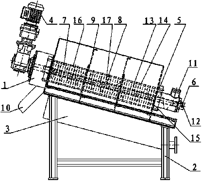
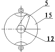
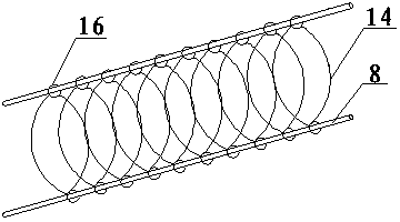
[0017] Such as figure 1 The sludge dehydrator shown in the figure can reduce the water content of sludge, including a body 1, a bracket 2, and a liquid collection and return device 3. The body 1 is arranged parallel to the upper part of the support 2, and the liquid collection and return device 3 is arranged below The body 1 includes a cam driving device 5, a connecting shaft 14, a screw propeller 6, a fixed ring 7, a moving ring 8 and a support vertical plate 9, and mud outlets 10 and mud inlets 11 are respectively provided at both ends, The body 1 is evenly provided with several support vertical plates 9, and several fixed shafts are arranged between the support vertical plates 9, and the fixed shafts are connected with the fixed ring 7, and the upper and lower ends of the support vertical plates 9 are provided with connecting shafts 14, which connect several The swimming ring 16 with the circular buckle and the cam driving device 5 and the cam driving baffle plate 15 at bot...


PUM


Abstract

The invention relates to a sludge dewatering machine, particularly a sludge dewatering machine capable of lowering sludge water content, which comprises a machine body (1), a bracket (2) and a liquid collection reflux unit (3). The sludge dewatering machine is characterized in that the machine body (1) is arranged above the bracket (2) in parallel, and the liquid collection reflux unit (3) is arranged below the bracket (2); the machine body (1) comprises a cam driving gear (5), a connecting shaft (14), a screw propeller (6), fixed rings (7), floating rings (8) and support vertical plates (9); both ends of the machine body (1) are respectively provided with a sludge outlet (10) and a sludge inlet (11); the machine body (1) is uniformly provided with the plurality of support vertical plates (9); a plurality of fixed shafts are arranged between every two support vertical plates (9); each fixed shaft is connected with the corresponding fixed ring (7); the upper and lower ends of each support vertical plate (9) are provided with the connecting shaft (14) which is used for connecting and fixing the floating rings (8) with circular slipknots (16) to the cam driving gear (5) and a cam driving baffle (15) on both ends; the distance between every two floating rings (8) is the thickness of one fixed ring (7); and one end of a screw shaft (12) is arranged in the screw propeller (6), and the other end is connected with a motor (4) through the cavities of the fixed rings (7) and floating rings (8). Compared with the prior art, the sludge dewatering machine has the advantage of no wear, reduces the water content, is simple to operate and easy to replace, and lowers the cost.

Description

technical field [0001] The invention relates to a sludge dewatering machine, more precisely a sludge dewatering machine capable of reducing the water content of the sludge. Background technique [0002] At present, the screw stack sludge dewatering machine of the existing technology on the market can be widely used in the dehydration of oily sludge with different concentrations, high and low viscosities, and oily sludge in all walks of life. It is composed of a fixed ring and a moving ring outside the screw shaft. Through the continuous rotation of the screw shaft, it can squeeze the sludge. Although the sludge dehydrator with this structure has many advantages, it has very obvious defects. , the spiral blades and rings that are constantly rotating during the working process are extremely easy to wear, and the normal continuous service life is less than 3600 hours. After the wear reaches a certain level, the equipment cannot achieve the expected treatment effect, and the...

Claims


Application Information

Patent Timeline
IPC IPC(8): C02F11/12
Inventor 张建军孙丽萍
Owner TAIZHOU LANHAI ENVIRONMENTAL PROTECTION TECH
Why Eureka
Try Eureka