Control system for blowing of copper converter

A converter blowing and control system technology, applied in the field of copper concentrate smelting, can solve problems such as air pollution, inaccurate judgment of the end point, frequent tilting of the furnace body, etc., and achieve the effect of ensuring safe production and improving efficiency

Active Publication Date: 2014-03-26
HEFEI GOLD STAR MECHATRONICS TECH DEV CO LTD
View PDF2 Cites 13 Cited by
  • Summary
  • Abstract
  • Description
  • Claims
  • Application Information

AI Technical Summary

Problems solved by technology

Manual sampling is easily affected by the mental state of the operator and personal practical experience, resulting in inaccurate judgment of the end point, low hit rate, and easy to cause safety hazards such as overblowing, "cold furnace" or "spray furnace".
At the same time, the hit rate is low, and repeated sampling is required, which forces frequent tilting of the furnace body, and a large amount of smelting waste gas is discharged from the furnace mouth, causing air pollution and affecting the health of operators.

Method used


Image

  • Control system for blowing of copper converter
  • Control system for blowing of copper converter
  • Control system for blowing of copper converter

Examples


Embodiment 1

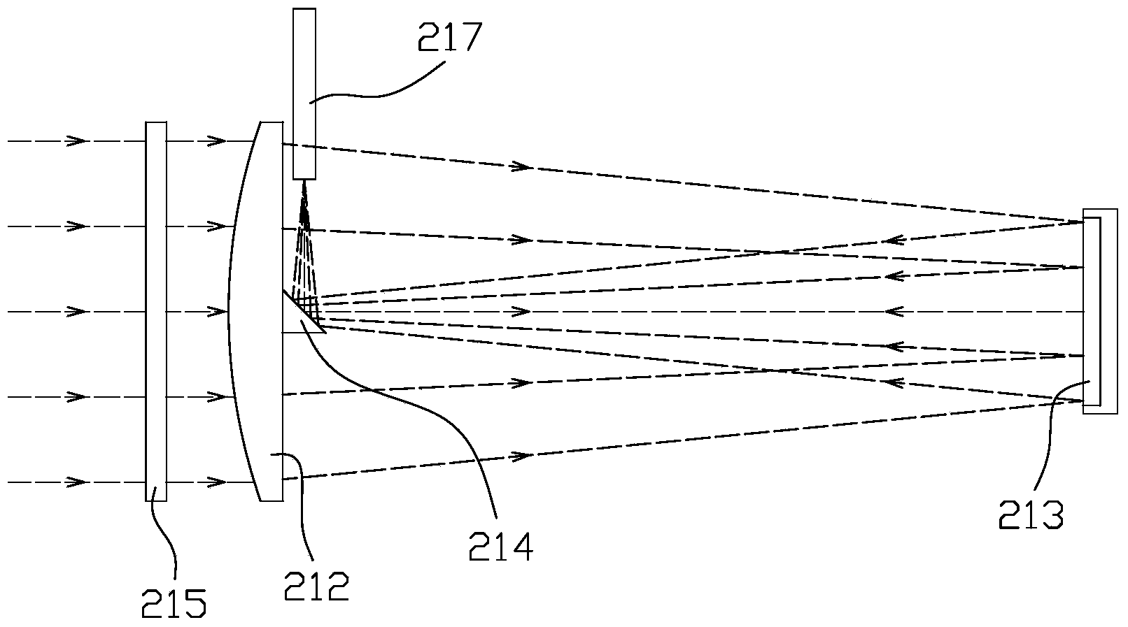
[0030] In the first embodiment, the mirror 214 is bonded to the lens 212 and arranged on a side close to the plane mirror 213, and the centers of the lens 212, the plane mirror 213 and the mirror 214 are located on the same straight line, and the optical path diagram is as follows figure 1 shown. When the reflector 214 is arranged on one side of the lens 212 instead of the peripheral position, the reflector 214 can block the incident light to a certain extent, but because the size of the reflector 214 is very small, the light blocked by it is very little and can be ignored; When this optical path is adopted for design, the structure of the lens barrel 211 is simple, and the arrangement of the optical fiber 217 is more convenient.

Embodiment 2

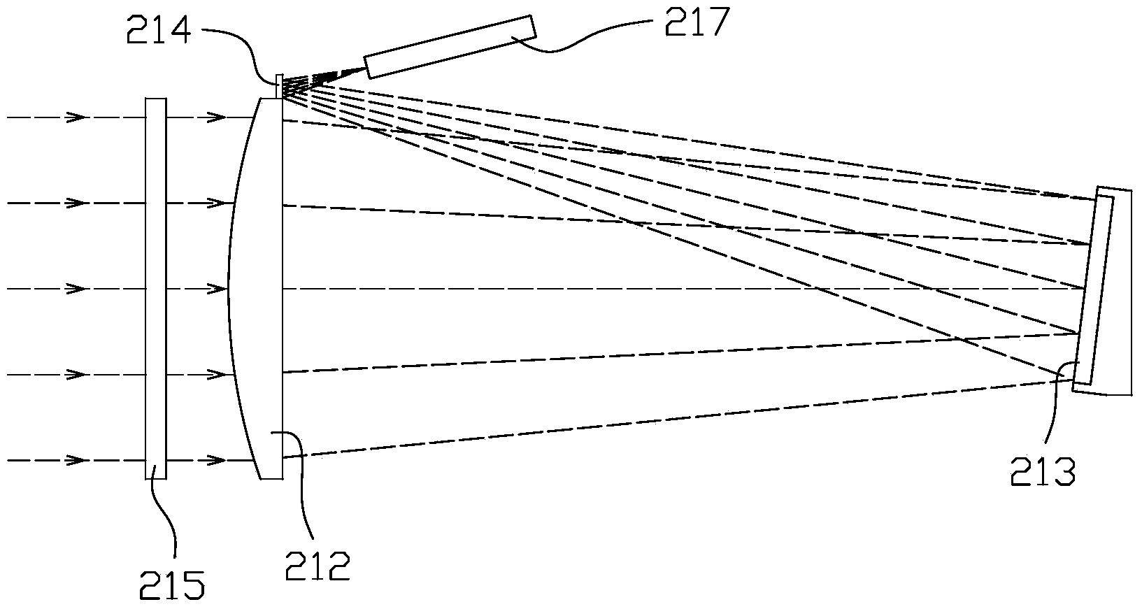
[0031] In the second embodiment, the reflector 214 is located adjacent to the periphery of the lens 212, and the plane reflector 213 forms a certain angle with the axis of the lens barrel 211, and the angle makes the plane reflector 213 emit light To the reflector 214, the light path diagram is as follows figure 2 shown. When using this optical path design, since the oblique line is longer than the straight line, the lens barrel 211 can be further shortened, and the mirror 214 is arranged around the lens 212, which will not block the incident light. Therefore, the structure of the lens barrel 211 and the arrangement of the optical fiber 217 are more complicated than those in the first embodiment.

[0032] refer to Figure 4 , Figure 5 , Figure 6 , in comparison, the arrangement of the optical fiber 217 and the structure of the lens barrel 211 are simpler and easier to design by adopting the scheme in the first embodiment. The following will describe in detail by taking ...


PUM


Abstract

The invention discloses a control system for the blowing of a copper converter. The control system comprises a slag forming endpoint detection unit, a copper forming endpoint detection unit and a data processing unit, wherein the slag forming endpoint detection unit is used for acquiring characteristic spectrum emission intensity signals of PbO and PbS in melt in the copper converter on line in a slag forming period; the copper forming endpoint detection unit is used for acquiring a concentration signal of SO2 in the flue gas of the copper converter on line in a copper forming period; the data processing unit is used for performing analytical processing to judge whether the signals acquired by the slag forming endpoint detection unit and the copper forming endpoint detection unit reach slag and copper forming endpoints or not and whether to stop blowing or not. According to the control system, the slag and copper forming endpoints in a blowing process of the copper converter can be accurately judged, so that the phenomena of over-blowing, under-blowing and the like are avoided, the safety production of blowing of the copper converter is ensured, and the copper smelting efficiency is improved.

Description

technical field [0001] The invention relates to the technical field of copper concentrate smelting, in particular to a control system for copper converter blowing. Background technique [0002] Copper matte converting mainly adopts PS converter converting technology. At present, 80% of the global mineral crude copper production capacity is using PS converter converting. Matte blowing is carried out in cycles, divided into slag-making period and copper-making period. In the slag-making period, air or oxygen-enriched air is blown into the melt in the furnace from the tuyere, and the air in the matte is stirred by the air. FeS is oxidized to form FeO and SO 2 ; FeO and SiO in the added flux 2 Carry out slagging reaction. Once the slagging reaction is over, the air supply is temporarily stopped and the slagging operation is carried out. During the copper-making period, the white matte (mainly Cu 2 Existing in the form of S) reacts with the oxygen in the blown air to form bl...

Claims


Application Information

Patent Timeline
Patent Type & Authority Applications(China)
IPC IPC(8): C22B15/06
Inventor 吴华峰高闽光王锋平张玉钧李相贤刘文清常国涛宋修明吴文明盛放魏庆农黄永峰
Owner HEFEI GOLD STAR MECHATRONICS TECH DEV CO LTD
Why Eureka
Try Eureka