Forced lubrication system for cutting speed reducer of tunneller

A technology of forced lubrication and reducer, which is applied in gear lubrication/cooling, cutting machinery, driving devices, etc., can solve the problem that the bearings at the high-speed end or low-speed end of the reducer at the cutting part cannot be lubricated, and achieve heat reduction and seal protection Effect

Inactive Publication Date: 2014-03-26
SHENYANG NORTH MINING MACHINERY
View PDF0 Cites 2 Cited by
  • Summary
  • Abstract
  • Description
  • Claims
  • Application Information

AI Technical Summary

Problems solved by technology

[0003] The purpose of the present invention is to provide a forced lubrication system for the cutting part reducer of the roadheader, which solves the problem that the bearings at the high-speed end or low-speed end of the cutting part reducer cannot be lubricated when the traditional excavation is mining in a large-slope roadway

Method used


Image

  • Forced lubrication system for cutting speed reducer of tunneller
  • Forced lubrication system for cutting speed reducer of tunneller
  • Forced lubrication system for cutting speed reducer of tunneller

Examples


Embodiment Construction

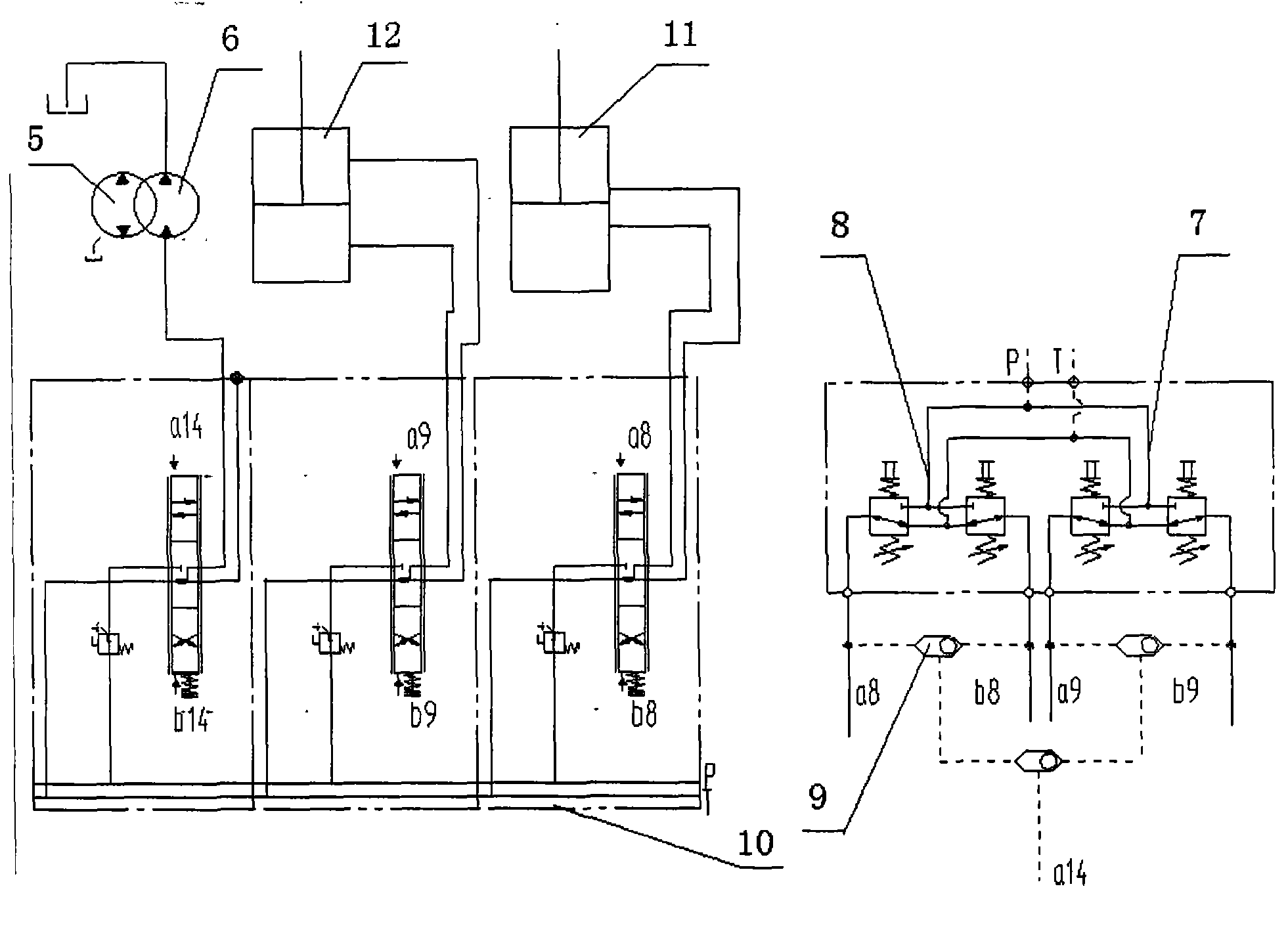
[0016] Such as figure 1 As shown, when the pilot valve 7 of the cutting head rotary cylinder or the pilot valve 8 of the cutting head lifting cylinder is pulled to control the multi-way valve 10 to make the cutting head rotary cylinder 11 or the cutting head lifting cylinder 12 act, the pilot oil passes through the shuttle The valve also controls the multi-way valve 10 to make the lubricating oil circulation pump drive motor 6 work.

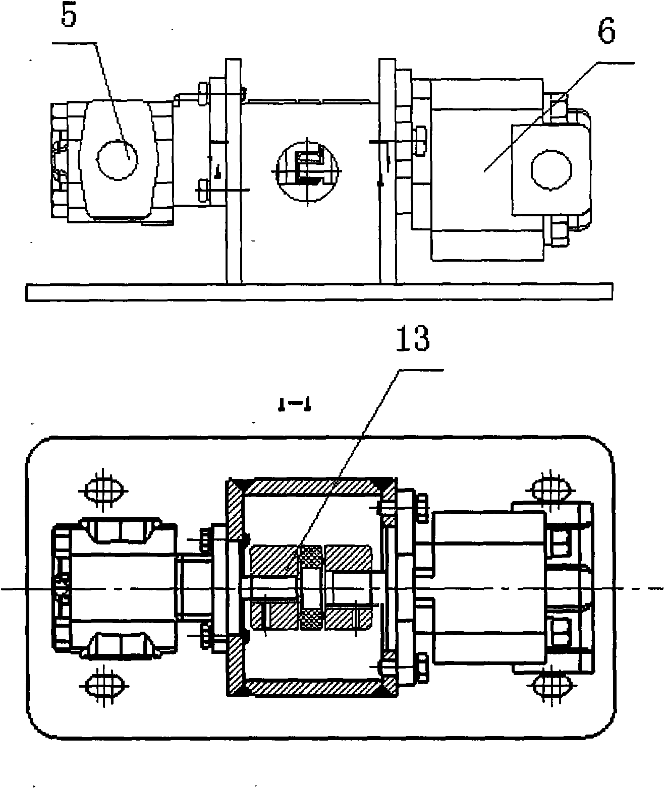
[0017] Such as figure 2 As shown, the lubricating oil circulating pump driving motor 6 drives the lubricating oil circulating pump 5 to work through the coupling 13 .

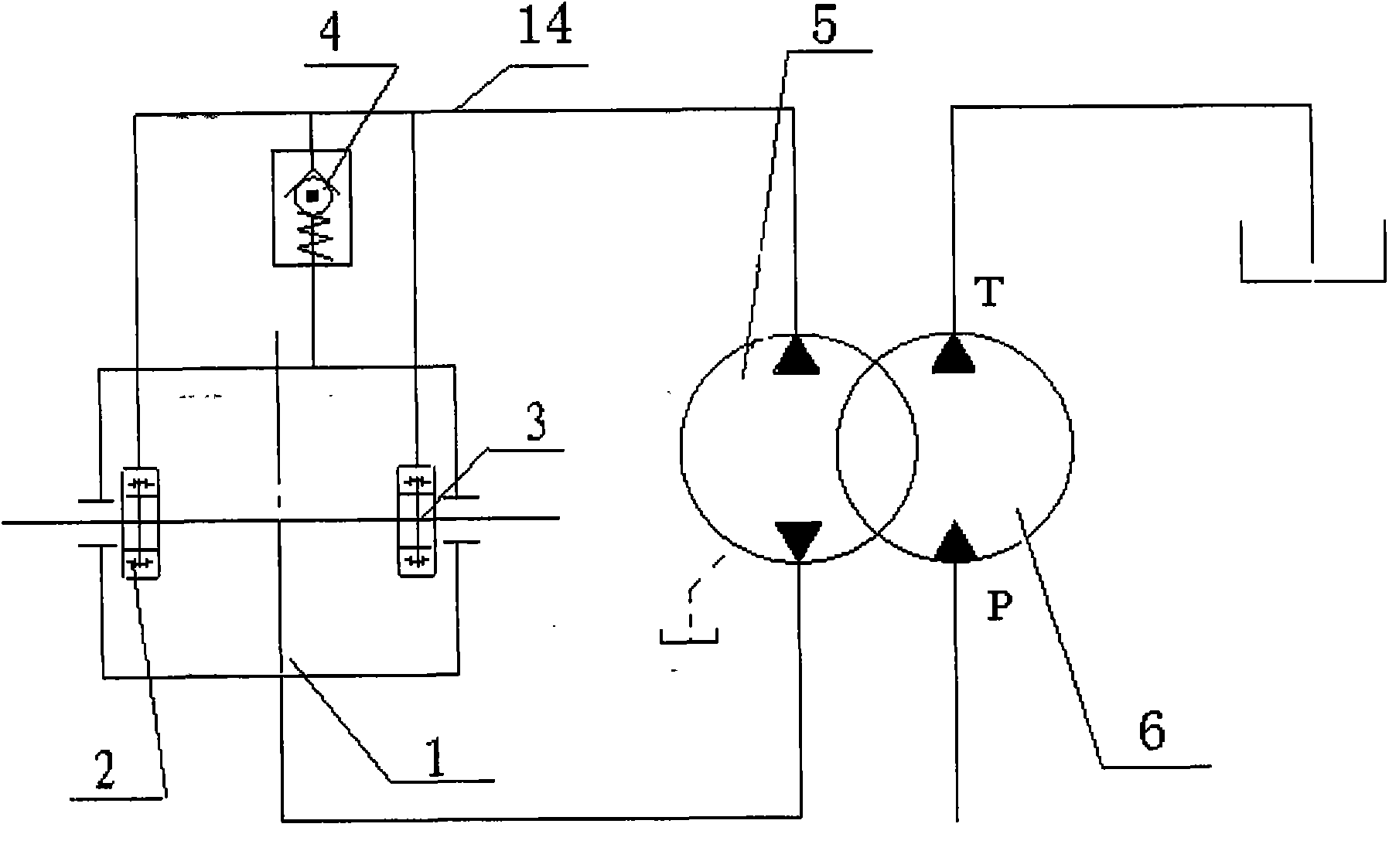
[0018] Such as image 3 As shown, the lubricating oil circulation pump 5 circulates the lubricating oil from the bottom of the cutting reducer 1 through the lubricating pipeline 14 to the bearing chambers of the low-speed end bearing 2 of the reducer and the high-speed end bearing 3 of the reducer for lubrication, and passes through the check valve Make the excess lubricating ...


PUM


Abstract

The invention relates to excavating and mining of large-slope coal mine tunnels, in particular to a forced lubrication system for the cutting speed reducer of a tunneller and solves the problem that when a traditional tunneller works at a slope of above 23 degrees, the bearing at the high-speed end or the low-speed end of the cutting speed reducer cannot be lubricated. Through the adoption of the forced lubrication system, the bearing at the high-speed end or the low-speed end of the cutting speed reducer can be lubricated above the level of lubricating oil. In a large-slope tunnel, when the tunneller goes up a slope to cut a roof, the bearing at the low-speed end of the cutting speed reducer is below the level of lubricating oil and thus cannot be lubricated; when the tunneller goes down the slope and the cutting head performs bottom sweeping, the bearing at the high-speed end of the cutting speed reducer is below the level of the lubricating oil and thus cannot be lubricated. A lubricating pump is driven by the hydraulic motor of a hydraulic system; when a cutting arm goes up and down, or rotates, lubricating oil at the bottom of the cutting speed reducer is pumped to the bearing cavities at the high-speed end and the low-speed end of the cutting speed reducer so as to provide forced lubrication for the bearings at the high-speed end and the low-speed end.

Description

technical field [0001] The invention relates to excavation and mining of roadways in large-slope coal mines, in particular to a forced lubrication of cutting reducer of roadheader and its control system. The hydraulic system controls the lubricating oil circulation pump to provide lubricating oil for the bearings at the high-speed end or low-speed end of the cutting speed reducer of the roadheader. , When mining up and down slopes in large-slope roadways, the bearings at the high-speed end or low-speed end of the cutting reducer can be effectively lubricated above the lubricating oil level and the temperature rise caused by circulation can be effectively controlled. Background technique [0002] At present, due to the complex roadway conditions of various coal mines, some coal mine roadway slopes are above 18°, so that when the roadheader is mining, the high-speed end and low-speed end bearings of the cutting reducer cannot be effectively lubricated, causing the reducer beari...

Claims


Application Information

Patent Timeline
Patent Type & Authority Applications(China)
IPC IPC(8): E21C31/02F16H57/04
Inventor 曲凯欧玉金莫彦青王艳丹杨华林
Owner SHENYANG NORTH MINING MACHINERY
Why Eureka
Try Eureka