
Compressor piston

A technology for compressors and pistons, which is applied in the field of pistons for compressors, and can solve problems such as lack of oil in the crankshaft cavity and insufficient lubricating oil.

Inactive Publication Date: 2016-07-27
SANDEN HUAYU AUTOMOTIVE AIR CONDITIONING CO LTD
View PDF8 Cites 0 Cited by
  • Summary
  • Abstract
  • Description
  • Claims
  • Application Information

AI Technical Summary

Problems solved by technology

[0003] However, since the lubricating oil flows in the same direction as the refrigerating gas in the compressor, the lubricating oil in the crank chamber gradually moves to the exhaust chamber, and the crank chamber is short of oil, so it cannot provide sufficient lubricating oil to the second groove 17 in time.

Method used


Image

  • Compressor piston
  • Compressor piston
  • Compressor piston

Examples


Embodiment 1

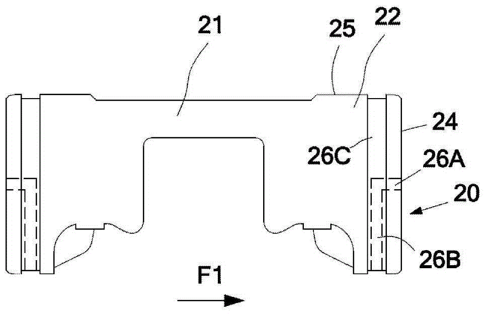
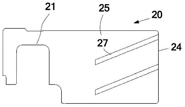
[0021] Figure 1 to Figure 2 An embodiment of the present invention is shown, and it should be noted that these and other subsequent drawings are only examples, they are not drawn in isometric conditions, and should not be taken as protection for the actual requirements of the present invention Scope constitutes a limitation.

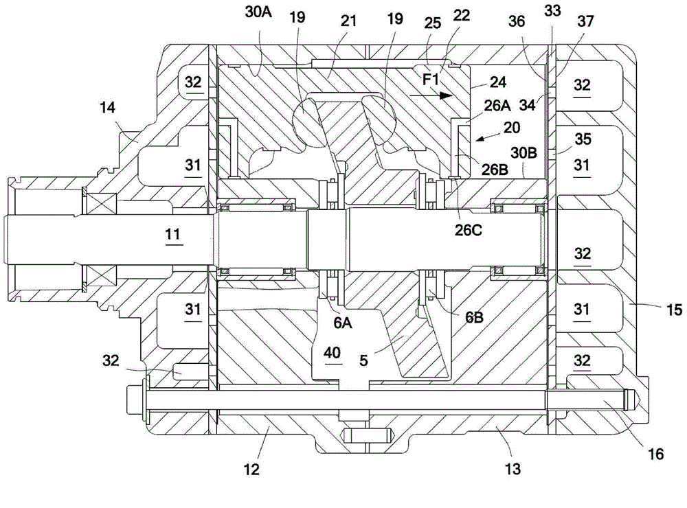
[0022] like figure 1 Shown is a cross-sectional view of a bidirectional swash plate compressor used in a vehicle air conditioner. The bidirectional swash plate type compressor has a pair of front cylinder blocks 12 and rear cylinder blocks 13 , and bolts 16 fasten the front cylinder block 12 and the rear cylinder block 13 together to form a swash plate cavity 40 . The drive shaft 11 penetrates the swash plate 5 , the front thrust bearing 6A, and the rear thrust bearing 6B, and the front thrust bearing 6A and the rear thrust bearing 6B are respectively supported by the front cylinder block 12 and the rear cylinder block 13 . The front and rear covers...


PUM


Abstract

The invention aims at providing a compressor piston. Lubricating oil can be provided for the piston via a cylinder hole or an exhaust cavity, so that the piston is sufficiently lubricated. In order to achieve the purpose, the compressor piston comprises a piston seat and a piston head, wherein the piston seat is used for being matched with a driving mechanism so as to enable the piston to move in the cylinder hole in a reciprocating manner; the piston head is used for forming sliding contact with the cylinder hole; and the piston head comprises an outer circumferential surface and an end surface. The compressor piston is characterized in that the piston head is further provided with a lubricating channel which connects the end surface with the outer circumferential surface.

Description

technical field [0001] The present invention relates to a piston for a compressor. Background technique [0002] The Chinese patent application document whose application number is CN96190823.8 and whose publication number is CN1163655A proposes a compressor piston, such as Figure 4 As shown, a circumferentially extending first groove 16 and an axially extending second groove 17 are formed on the circumferential surface of the piston 11 . Since the second groove 17 communicates with the crankshaft cavity of the compressor intermittently during the reciprocating motion of the piston 11, the lubricating oil in the crankshaft cavity can be stored in the second groove 17 and flow to the first groove 16, so that the circumferential surface of the piston Most of the area is lubricated. [0003] However, since the lubricating oil flows in the same direction as the refrigerant gas in the compressor, the lubricating oil in the crankshaft chamber gradually moves to the exhaust chamb...

Claims


Application Information

Patent Timeline
Patent Type & Authority Applications(China)
IPC IPC(8): F04B39/00F04B39/02
Inventor 陶明飞
Owner SANDEN HUAYU AUTOMOTIVE AIR CONDITIONING CO LTD
Learn More