
Eureka
For R&D, Eureka makes reading and utilizing patents & technical documents easy.
Eureka AIR
Designed for self-driven R&D workflows. Generate viable solutions, solve complex R&D challenges, empower your innovation with AI.

Eureka Materials
Designed for material experts only. Revolutionize your material R&D, from search, analyze, to developing new materials.

TechResearch
Generate reliable direction feasibility study reports for your R&D in just a few steps.

TechSeek
Discover and master advanced knowledge NOW. Basics, ideas, possibilities, all at once.

TechMind
As an expert in R&D Theories, TechMind can generates customized viable solutions instantly.

TechRisk
Analyze your overall solution with one click, know your potential R&D risks in advance.

TechMonitor
Get weekly tech updates, stay abreast of the latest tech innovations and key insights.
Valve timing control apparatus
A control device, valve timing technology, applied in the direction of valve devices, engine components, machines/engines, etc.
- Summary
- Abstract
- Description
- Claims
- Application Information
AI Technical Summary
Problems solved by technology
Method used
Image

Examples
Embodiment Construction
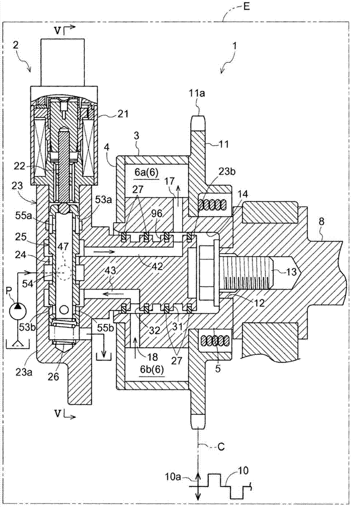
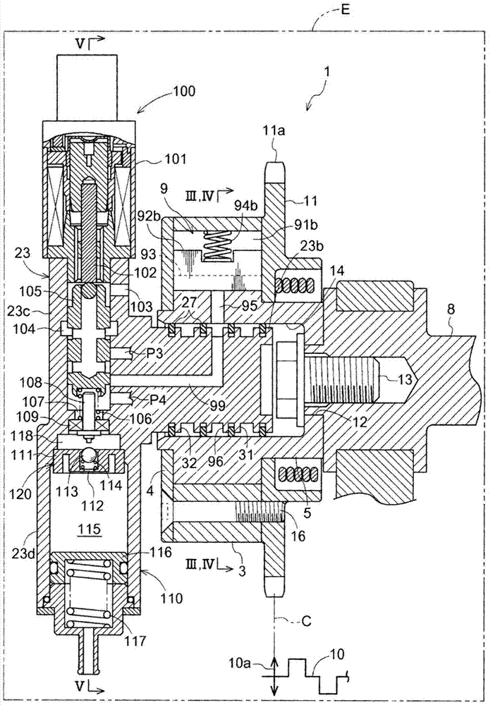
[0028] will refer to figure 1 The valve timing control device 1 according to the first embodiment is described through FIG. 6 .
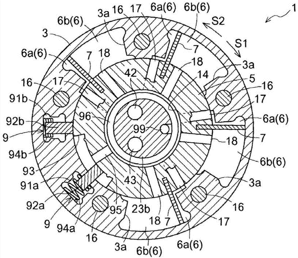
[0029] Such as figure 1 and figure 2 As shown, the valve timing control device 1 includes an outer rotor 3 as a driving-side rotating member and an inner rotor 5 as a driven-side rotating member. The outer rotor 3 rotates synchronously with a crankshaft 10 of the engine E as an internal combustion engine. The inner rotor 5 is provided coaxially with the outer rotor 3 to rotate synchronously with a camshaft 8 for opening and closing valves of the engine E. As shown in FIG.
[0030] The inner rotor 5 is integrally assembled on the end of a camshaft 8 serving as a rotating shaft of a cam for controlling opening and closing of an intake valve or an exhaust valve of the engine E. The inner rotor 5 coaxially includes a recess 14 recessed from the side facing the front plate 4 . A fixing hole 12 is formed at the bottom surface of the recess 14 to pen...
PUM
 Abstract
Description
Claims
Application Information
 - R&D Engineer
- R&D Manager
- IP Professional
- Industry Leading Data Capabilities
- Powerful AI technology
- Patent DNA Extraction
Browse by: Latest US Patents, China's latest patents, Technical Efficacy Thesaurus, Application Domain, Technology Topic, Popular Technical Reports.
© 2024 PatSnap. All rights reserved.Legal|Privacy policy|Modern Slavery Act Transparency Statement|Sitemap|About US| Contact US: help@patsnap.com