Integrated hydraulic transformer

A hydraulic transformer, integrated technology, applied in the field of hydraulic components, can solve the problems of large noise and small range of voltage regulation ratio of the transformer, and achieve the effect of eliminating noise, eliminating throttling loss, and simplifying the oil circuit

Inactive Publication Date: 2014-03-26
HARBIN UNIV OF SCI & TECH
View PDF5 Cites 5 Cited by
  • Summary
  • Abstract
  • Description
  • Claims
  • Application Information

AI Technical Summary

Problems solved by technology

[0005] The purpose of the present invention is to provide an integrated hydraulic transformer to solve the problems of throttling loss in existing hydraulic transformers, small range of voltage regulation ratio of the transformer, and large noise during operation

Method used


Image

  • Integrated hydraulic transformer
  • Integrated hydraulic transformer
  • Integrated hydraulic transformer

Examples


specific Embodiment approach 1

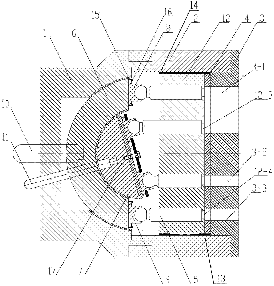
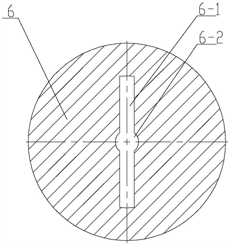
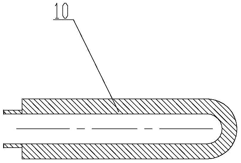
[0015] Specific embodiment one: combination Figure 1-Figure 6 To illustrate this embodiment, this embodiment includes a left end cover 1, a housing 2 and a right end cover 3. The left end cover 1, the housing 2 and the right end cover 3 are connected in sequence from left to right, and the inside constitutes a closed cavity of the hydraulic transformer. The hydraulic transformer also includes a valve plate 4, an outer annular swash plate 6, an inner annular swash plate 7, an outer sliding shoe 8, an inner sliding shoe 9, an outer swash plate adjusting rod 10, an inner swash plate adjusting rod 11, a cylinder body 12 and more There are two plungers 5, the outer annular swash plate 6 is rotatably arranged in the left end cover 1, the inner annular swash plate 7 is arranged on the outer annular swash plate 6, and the inner annular swash plate 7 is arranged concentrically with the outer annular swash plate 6, and the outer swash plate The adjusting rod 10 passes through the left e...

specific Embodiment approach 2

[0017] Specific implementation manner two: combination figure 1 Explain that the right end cover 3 of this embodiment is provided with a first pressure notch 3-1, a second pressure notch 3-2, and a third pressure notch 3-3. The first pressure notch 3-1, The second pressure notch 3-2 and the third pressure notch 3-3 are both arc-shaped pressure notches, and the first pressure notch 3-1 is located on one side of the center line of the right end cover 3, and the second pressure notch 3 -2 and the third pressure notch 3-3 are located on the other side of the center line of the right end cover 3. The purpose of this embodiment is to facilitate the overall operation of the hydraulic transformer. The technical features not disclosed in this embodiment are the same as the first embodiment.

specific Embodiment approach 3

[0018] Specific implementation mode three: combination figure 1 , Figure 4 with Figure 5 It is explained that the distribution plate 4 of this embodiment is provided with an integrated notch 4-1, a first sub-notch 4-2, and a second sub-notch 4-3, and the integrated notch 4-1 and the first sub-notch 4 -2 and the second sub-notch 4-3 respectively match the structure and size of the first pressure notch 3-1, the second pressure notch 3-2, and the third pressure notch 3-3. The technical features not disclosed in this embodiment are the same as those in the second embodiment.


PUM


Abstract

The invention discloses an integrated hydraulic transformer, relates to a hydraulic transformer, and aims to solve the problems that throttling losses exist in an existing transformer, and the transformer is small in regulating ratio range and large in noise in the operating process. A left end cover, a shell and a right end cover are sequentially connected from left to right, an outer annular swash plate is rotatably arranged in the left end cover, an inner annular swash plate is arranged on the outer annular swash plate, an outer swash plate adjusting rod penetrates through the left end cover and is connected with the outer annular swash plate, an inner swash plate adjusting rod sequentially penetrates through the left end cover and the outer annular swash plate and then is connected with the inner annular swash plate, a cylinder block and a thrust plate are sequentially arranged in a sealing inner cavity from left to right, a needle bearing is externally arranged on the cylinder block, one ends of a plurality of plungers are matched with plunger holes in the cylinder block, the other ends of the plungers are hinged to piston shoes, and the piston shoes are restrained on the swash plates through inner baffle rings and outer baffle rings. The integrated hydraulic transformer is used for hydraulic transformation.

Description

Technical field [0001] The invention relates to a hydraulic component, in particular to an integrated hydraulic transformer. Background technique [0002] The constant pressure network secondary adjustment technology developed in recent years has improved the flexibility and efficiency of the hydraulic system. However, although the principle of secondary regulation has many advantages, its application in the hydraulic field has been limited. In terms of driving the rotating load, the driving of the rotating load can be achieved by adjusting the adjustment mechanism of the variable hydraulic motor. The traditional method of driving linear loads with different load pressure requirements is through a throttle control method. Because the throttle control method has a large pressure difference, this control method brings a greater energy loss. How to transmit the energy of the constant voltage network like a power transformer or a mechanical gear transmission with a certain pressure...

Claims


Application Information

Patent Timeline
Patent Type & Authority Applications(China)
IPC IPC(8): F15B3/00
Inventor 邵俊鹏安光明
Owner HARBIN UNIV OF SCI & TECH
Why Eureka
Try Eureka