An integrated hydraulic transformer
A hydraulic transformer and integrated technology, applied in the field of hydraulic components, can solve the problems of high noise and small voltage regulation ratio of the transformer, and achieve the effects of eliminating noise, eliminating throttling loss and having a simple structure
- Summary
- Abstract
- Description
- Claims
- Application Information
AI Technical Summary
Problems solved by technology
Method used
Image
Examples
specific Embodiment approach 1
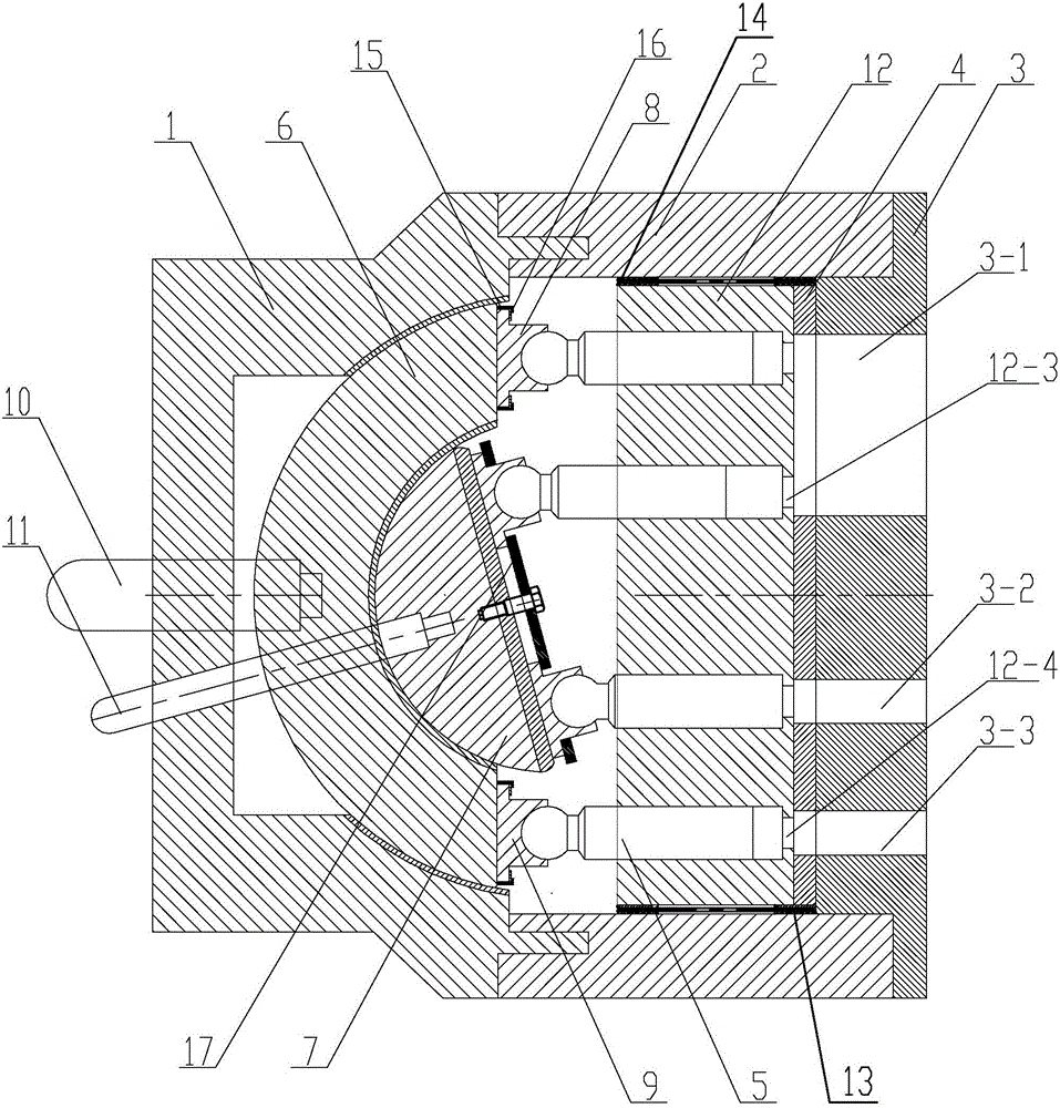
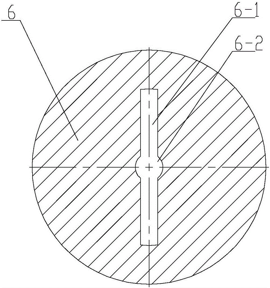
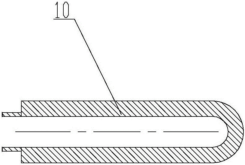
[0015] Specific implementation mode one: combine Figure 1-Figure 6 Describe this embodiment. This embodiment includes a left end cover 1, a housing 2 and a right end cover 3. The left end cover 1, housing 2 and right end cover 3 are sequentially connected from left to right, and the inside thereof constitutes a closed cavity of a hydraulic transformer. The hydraulic transformer also includes a distribution plate 4, an outer annular swash plate 6, an inner annular swash plate 7, an outer sliding shoe 8, an inner sliding shoe 9, an outer swash plate adjusting rod 10, an inner swash plate adjusting rod 11, a cylinder body 12 and multiple A plunger 5, the outer annular swash plate 6 is rotatably arranged in the left end cover 1, the inner annular swash plate 7 is arranged on the outer annular swash plate 6, and the inner annular swash plate 7 is concentrically arranged with the outer annular swash plate 6, and the outer swash plate The adjusting rod 10 passes through the left end...
specific Embodiment approach 2
[0017] Specific implementation mode two: combination figure 1 Explain that the right end cover 3 of this embodiment is provided with a first pressure notch 3-1, a second pressure notch 3-2 and a third pressure notch 3-3, the first pressure notch 3-1, The second pressure notch 3-2 and the third pressure notch 3-3 are arc-shaped pressure notches, and the first pressure notch 3-1 is located on the side of the centerline of the right end cover 3, and the second pressure notch 3 -2 and the third pressure notch 3-3 are located on the other side of the center line of the right end cover 3. The purpose of setting this embodiment in this way is to facilitate the overall operation of the hydraulic transformer. The undisclosed technical features in this embodiment are the same as those in the first embodiment.
specific Embodiment approach 3
[0018] Specific implementation mode three: combination figure 1 , Figure 4 and Figure 5 Description, the distribution plate 4 of the present embodiment is provided with an integrated notch 4-1, a first sub-notch 4-2 and a second sub-notch 4-3, an integrated notch 4-1, a first sub-notch 4 -2 and the second sub-notch 4-3 match the structure and size of the first pressure notch 3-1, the second pressure notch 3-2 and the third pressure notch 3-3 respectively. The undisclosed technical features in this embodiment are the same as those in the second embodiment.
PUM
 Abstract
Description
Claims
Application Information
 - R&D
- Intellectual Property
- Life Sciences
- Materials
- Tech Scout
- Unparalleled Data Quality
- Higher Quality Content
- 60% Fewer Hallucinations
Browse by: Latest US Patents, China's latest patents, Technical Efficacy Thesaurus, Application Domain, Technology Topic, Popular Technical Reports.
© 2025 PatSnap. All rights reserved.Legal|Privacy policy|Modern Slavery Act Transparency Statement|Sitemap|About US| Contact US: help@patsnap.com


