High-speed gearbox sealing device and high-speed gearbox with same

A sealing device and gearbox technology, applied in the field of rail vehicle drive train, can solve the problems that the gearbox is difficult to meet the application requirements of higher speed grades, it is difficult to meet the limit and light weight requirements of the gearbox, and the axial sealing size of the sealing device is large. , to achieve the effect of improving processing technology, compact structure and meeting design requirements

Active Publication Date: 2014-03-26
CRRC QISHUYAN INSTITUTE CO LTD +1
View PDF2 Cites 14 Cited by
  • Summary
  • Abstract
  • Description
  • Claims
  • Application Information

AI Technical Summary

Problems solved by technology

[0005] The existing public technology, such as patent 03131680.8, discloses a sealing device for a drive gearbox using a non-contact labyrinth sealing mechanism. The technical solution mainly has the following disadvantages: first, the non-contact labyrinth sealing mechanism consists The first dynamic oil seal ring, the second dynamic oil seal ring, the first static oil seal ring, the second static oil seal ring and the third static oil seal ring, and the three static oil seal rings are all made of aluminum alloy. Welded into one, it is difficult to guarantee the assembly accuracy requirements
Secondly, the sealing device needs to be equipped with a first dynamic oil seal ring, a second dynamic oil seal ring, and an oil deflector ring, all of which are sleeved on the shaft, resulting in a large axial seal size of the sealing device
Another example is patent 102062198A, which discloses a drive gearbox device including a non-contact mechanical labyrinth seal structure. The technical solution mainly has the following disadvantage...

Method used


Image

  • High-speed gearbox sealing device and high-speed gearbox with same
  • High-speed gearbox sealing device and high-speed gearbox with same
  • High-speed gearbox sealing device and high-speed gearbox with same

Examples


Embodiment Construction

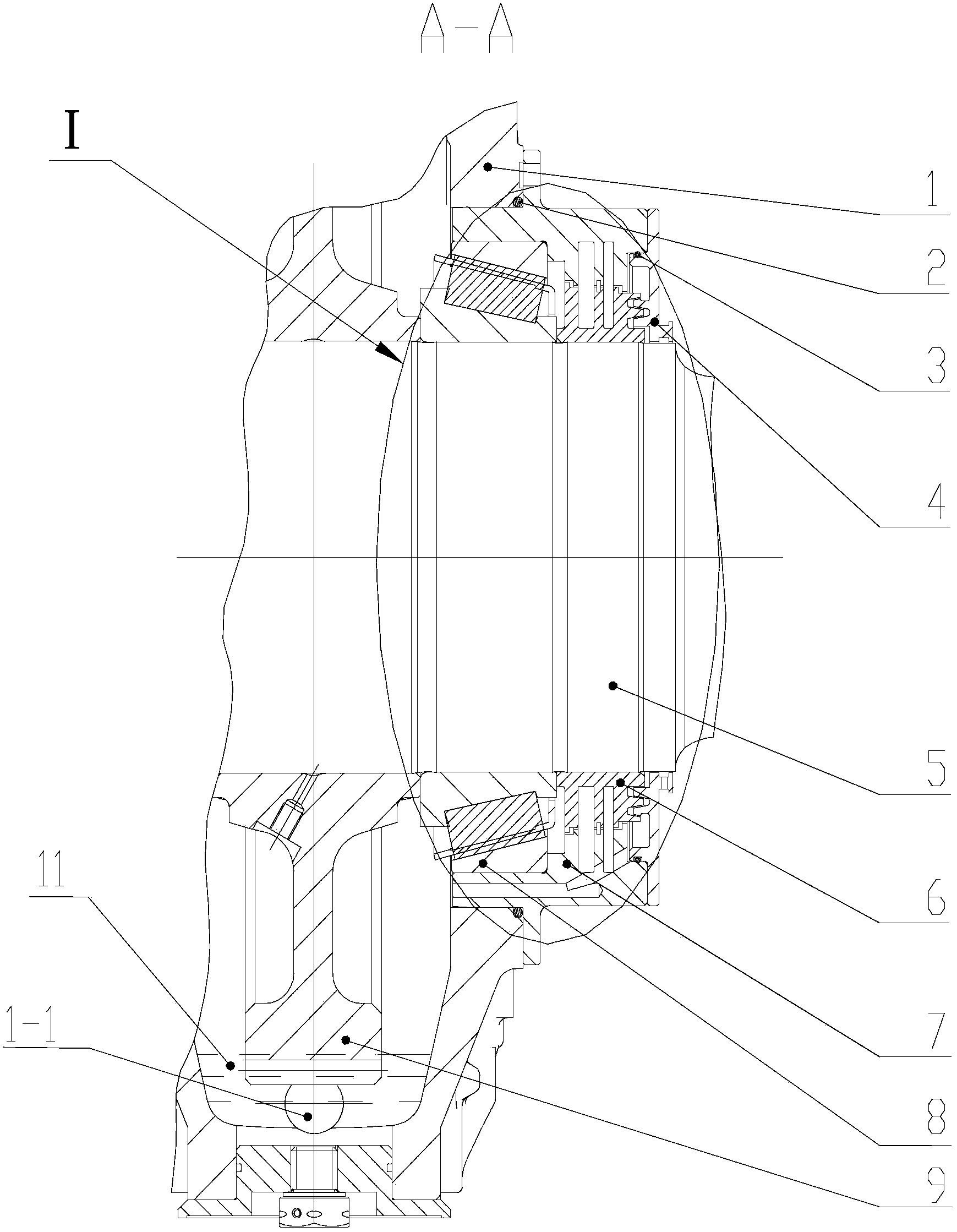
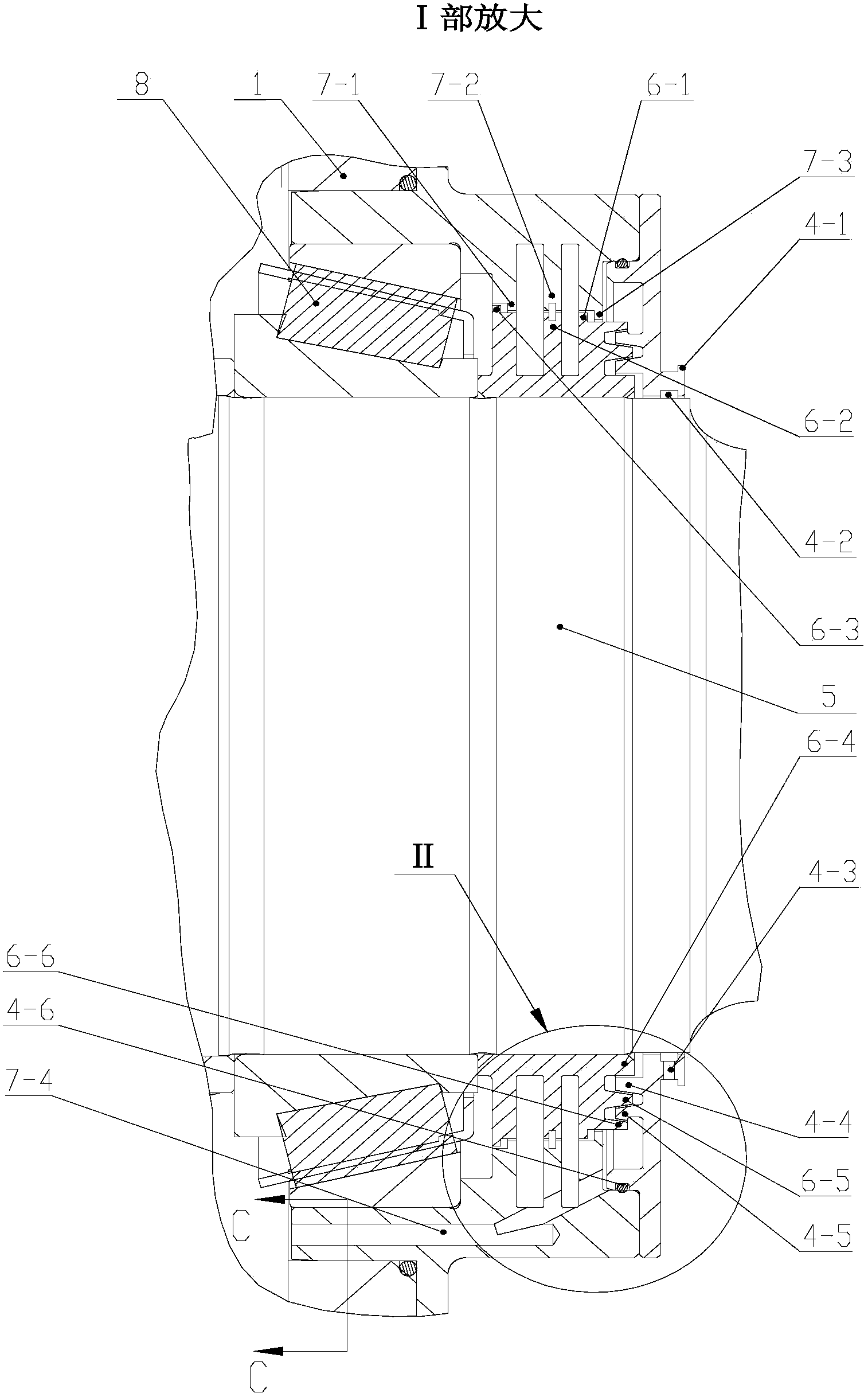
[0035] This embodiment discloses a high-speed gearbox sealing device, such as figure 1 , figure 2As shown, the sealing ring 6 set on the shaft 5, the bearing seat 7 installed on the box body 1, the sealing end cover 4 installed on the bearing seat 7, and the first O-ring sealing ring set on the bearing seat 7 2. It is composed of the second O-shaped sealing ring 3 sleeved on the sealing end cover 4 . The bearing seat 7 is provided with an inner hole for installing the bearing 8 . The sealing ring 6 and the bearing 8 are both sleeved on the shaft 5 and rotate together with the shaft 5 at high speed. The O-shaped seal ring 2 is sleeved on the bottom of the bearing seat 7, and is against the casing 1. The sealing device is provided with a plurality of protrusions, and the protrusions are respectively arranged on the bearing seat 7, the sealing ring 6, and the sealing end cover 4, which reduces the complexity and processing difficulty of the parts and improves the processabili...


PUM


Abstract

The invention discloses a high-speed gearbox sealing device and a high-speed gearbox with the high-speed gearbox sealing device. The high-speed gearbox sealing device comprises a gearbox body and a shaft, wherein the gearbox body and the shaft are arranged on the high-speed gearbox, and are connected with each other, a bearing block is fixed to the gearbox body, a sealing end cover is installed on the bearing block, the shaft is sleeved with a sealing ring, at least one labyrinth seal cavity, a labyrinth throttling cavity, an oil throwing pressure reduction cavity, a gap seal cavity and the like can be formed in the high-speed gearbox sealing device, at least one oil return hole is further formed in the high-speed gearbox sealing device, and the oil throwing pressure reduction cavity is communicated with the gearbox body through the oil return hole. According to the high-speed gearbox sealing device, contact type sealing and non-contact type sealing are combined, the axial size is small, sealing is safe and reliable, and the design requirement for gearboxes with the higher speed grade is well met.

Description

technical field [0001] The invention belongs to the technical field of rail vehicle drive trains, and in particular relates to a high-speed gearbox sealing device and a high-speed gearbox applying the device. Background technique [0002] As a key component of the EMU, the gearbox plays an important role in transmitting torque and driving the vehicle. Therefore, the operating state of the gearbox will affect the safety and reliability of the entire EMU. [0003] At present, the gear boxes of EMUs are all lubricated with oil. Leakage of lubricating oil will affect the service life of gears, bearings, etc., and may also pollute the environment. When external oil, water and other debris enter the gearbox, it will affect the performance of the lubricating oil, and will also affect the operation of the gears and bearings. Therefore, it is necessary to design a safe and reliable sealing device. The sealing device must ensure two-way sealing to effectively prevent the leakage of l...

Claims


Application Information

Patent Timeline
IPC IPC(8): F16H57/029F16H57/027F16H57/031F16H57/021F16H57/04F16H57/02
CPCF16H57/021F16H57/029F16H57/031F16H57/0423F16H57/0424F16H57/0449F16H57/0471F16H57/0472
Inventor 金思勤陈维金李枫王本涛吴成攀原治会刘莹吴宝贵
Owner CRRC QISHUYAN INSTITUTE CO LTD
Why Eureka
Try Eureka