An ultra-low energy consumption circulating fluidized bed air drying equipment
A circulating fluidized bed and airflow drying technology, which is applied in the direction of drying solid materials, lighting and heating equipment, heating to dry solid materials, etc., can solve the problem of limited effect, insufficient heat and moisture exchange speed between drying medium and materials, and drying equipment. The temperature of the surface and exhaust gas cannot be lowered to achieve the effect of low energy consumption
- Summary
- Abstract
- Description
- Claims
- Application Information
AI Technical Summary
Problems solved by technology
Method used
Image
Examples
no. 1 example
[0020] The first embodiment: an ultra-low energy consumption circulating fluidized bed airflow drying equipment.
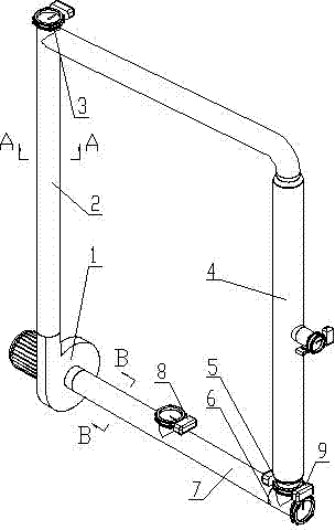
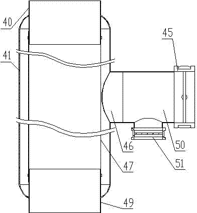
[0021] see Figure 1 to Figure 4 , the ultra-low energy consumption circulating fluidized bed air drying equipment includes fan 1, circulation pipeline I2, dust collector 4, regulating valve 5, inlet tee 6, circulation pipeline II7, the above components are blower 1 outlet, circulation pipe Road I2, dust collector 4 intake pipe 40, dust collector 4 ash discharge pipe 49, regulating valve 5, intake tee 6, circulation pipeline II7, fan 1 inlet are connected in sequence to form a circulation channel; circulation pipeline I2 and circulation pipe Road Ⅱ7 is wrapped with thermal insulation material glass wool felt 31, there is a discharge port on the circulation line Ⅰ2, and a discharge valve 3 is installed on the discharge port, there is a feeding port on the circulation line Ⅱ7, and a feeding valve 8 is installed on the feeding port. Another port of the tee 6 is an ...
no. 2 example
[0023] The second embodiment: another ultra-low energy consumption circulating fluidized bed airflow drying equipment.
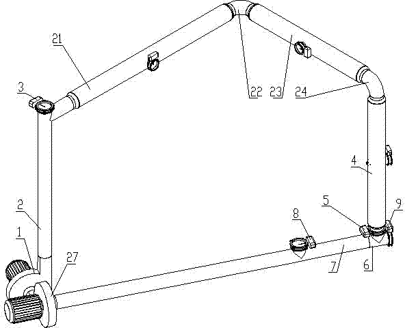
[0024] see Figure 5 and Figure 6 , the ultra-low energy consumption circulating fluidized bed air drying equipment includes fan 1, circulation pipeline I2, dust collector 4, regulating valve 5, intake tee 6, circulation pipeline II7, dust collector 21, pipeline A22, dust collector 23. Pipeline B24, fan 27, the above-mentioned components are according to fan 1 outlet, circulation pipeline I2, dust collector 21 intake pipe 40, dust collector 21 ash discharge pipe 49, pipe A22, dust collector 23 intake pipe 40, dust collector 23 dust discharge Pipe 49, pipe B24, dust collector 4 intake pipe 40, dust collector 4 ash discharge pipe 49, regulating valve 5, air intake tee 6, circulation pipeline II7, inlet of fan 27, outlet of fan 27, and inlet of fan 1 It forms a circulation channel; the circulation pipeline Ⅰ2 and the circulation pipeline Ⅱ7 are wrapped with...
PUM
 Abstract
Description
Claims
Application Information
 - R&D
- Intellectual Property
- Life Sciences
- Materials
- Tech Scout
- Unparalleled Data Quality
- Higher Quality Content
- 60% Fewer Hallucinations
Browse by: Latest US Patents, China's latest patents, Technical Efficacy Thesaurus, Application Domain, Technology Topic, Popular Technical Reports.
© 2025 PatSnap. All rights reserved.Legal|Privacy policy|Modern Slavery Act Transparency Statement|Sitemap|About US| Contact US: help@patsnap.com


